Omron V-TS Teaching Manual.pdf.pdf - 第34页
2.1 Bas ics of Teaching 2-7 90 ° 0 ° 180 ° 270 °
Chapter 2 Inspection Programming
2-6
Component Number
Inspection criteria and inspection windows must be specified by the unit of component number
in teaching.
A component number after teaching is registered in the library for reuse when additional
inspection programs are created.
Component Number Library
A library is provided for managing component number information. Component number
information is saved in the component number library. The inspection program obtains
component number information by referring to the component number library. The inspection
program itself does not have component number information. More than one component
number libraries can be created, and identified by the library number and library name. If the
system of component number names is different from each other among the customers,
manage the component numbers using separate component libraries.
Inspection Windows
Inspection windows can be categorized into several types including Inspection Region Window,
Component Body Window, Land Window and Electrode Window. Windows are positioned over
the PCB image, and inspection criteria is specified for each window.
Each window is displayed in a different color as shown below:
・White…Inspection Region Window, Component Body Window or Electrode Window
・Yellow…Land Window
・Light Blue…Selected window
In addition, there are windows with no inspection criterion in addition to the windows above,
displayed in the following colors, respectively:
- White: Component Body Plus Window, Lifted Component Window
- Gray: Component Body Minus Window, and Excluded Window (component number)
- Light green: Component Body Minus Window, Excluded Window (PCB)
- Yellow: Wrong Polarity/Height Reference Point Window
- Light Blue: Wrong Polarity/Height Measurement Point Window
Refer to the Inspection Logic Manual, "1.4 Component Types and Individual Windows" for the window
positioning procedure.
Model Calculation
The characteristic parameters used in inspection logics are automatically extracted based on
the windows and model images specified for individual component numbers. The extracted
characteristic parameters are registered in the library.
Refer to the Inspection Logic Manual, P1-2 "1.2 Inspection Parameter" for details on characteristic
parameters.
Component Angle
This system uses the symbols composed of "+" (representing the center of the component) and
"△" (direction) to show the component angles.
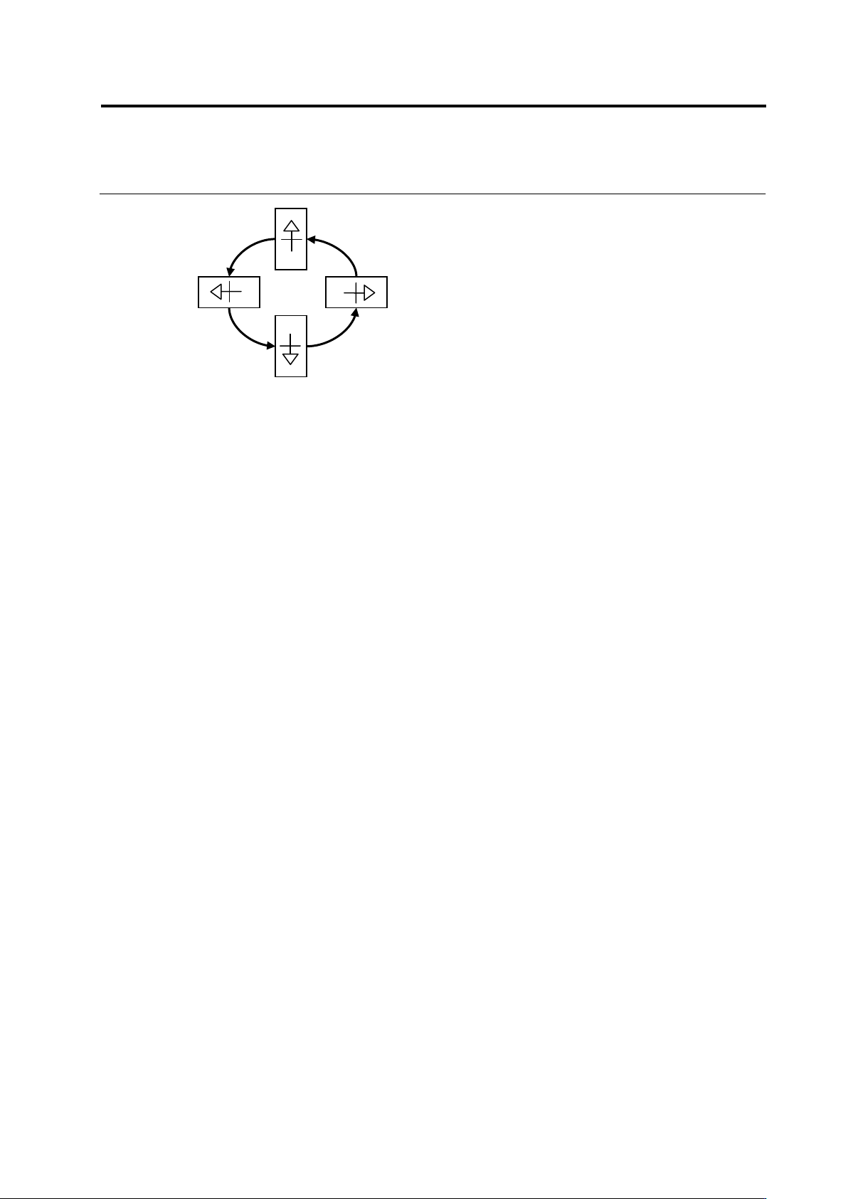
2.1 Basics of Teaching
2-7
90°
0°
180°
270°
Chapter 2 Inspection Programming
2-8
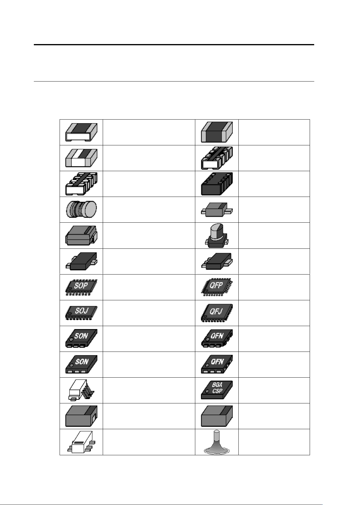
Component Types
This system classifies components under the following categories.
Component Type
Chip Resistor
Chip Capacitor
Other Chip Components
Resistor Array
(Micro-Lead)
Resistor Array (Castellated
Electrode)
Other Arrays (Non-Lead)
MELF Component
2 Pin Mini Mold Package
Inward L-Lead Package
Electrolytic Capacitor
Transistor
Power Transistor
SOP
QFP
SOJ
QFJ
SON (Micro-Lead)
QFN (Micro-Lead)
SON (Non-Lead)
QFN (Non-Lead)
Connector
BGA/CSP
Other Non-Lead Packages
Other Bottom Surface
Electrode Components
Other Lead Packages
Insertion Component