Omron V-TS Teaching Manual.pdf.pdf - 第87页
Chapter 2 Inspecti on Programm ing 2- 60 ・ A d just the Land Size Adjust the size of auto -extr acted land windows in ac cordance with the bare PCB im age. This operation is not usually required. Perform it only when the…
2.4 Registering for Inspection
2-59
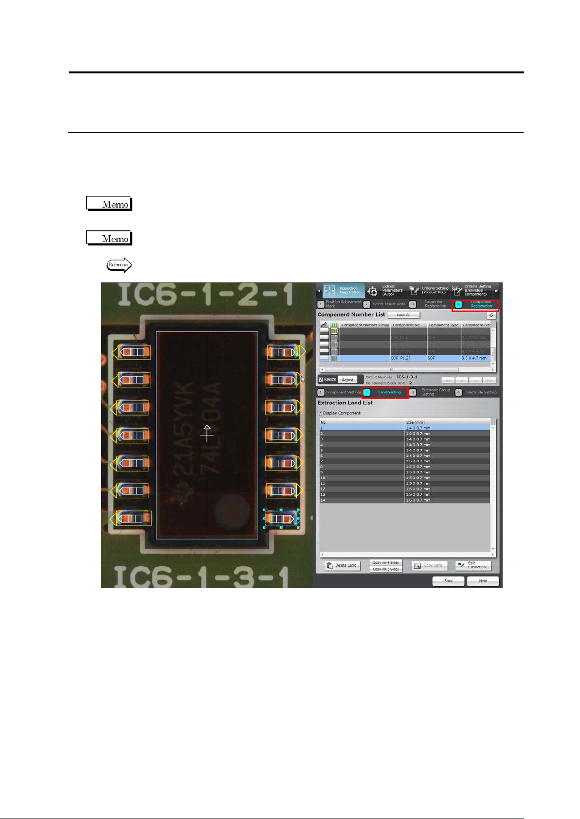
2.4.5.2 Land Setting
Land windows are automatically extracted and displayed on the screen, if they are not specified
for the component yet, based on the bare PCB image. The size and position of the auto-extracted
land windows can be adjusted on the screen.
You cannot select the target component on the land settings screen. To change the component,
click [Back] to return to the component settings screen and select a component, adjust the
Component Body Window, and then click [Next].
Land windows must be manually added or deleted, if the auto extraction failed (due to the wrong
number of land windows).
Refer to “Add a land window” or “Delete a land window” of “2.4.5.2 Land Setting” for the
procedures to add or delete land windows.
Chapter 2 Inspection Programming
2-60
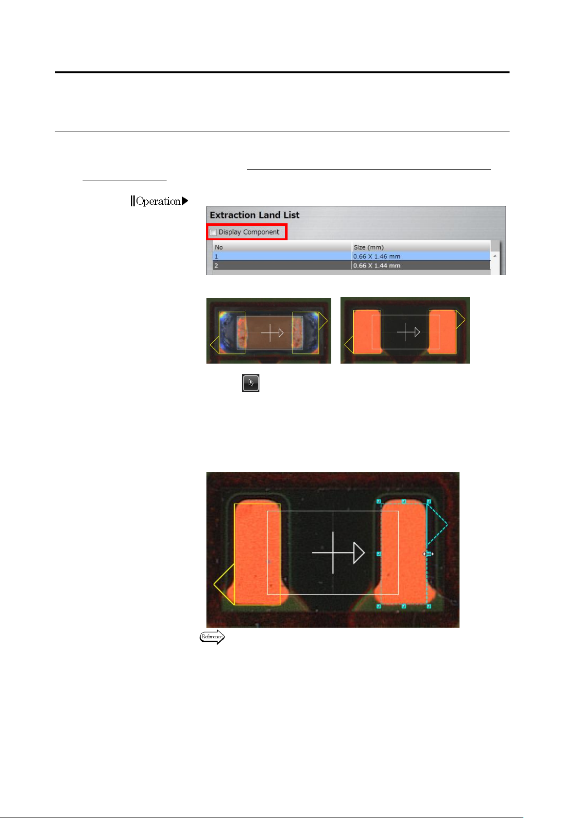
・ Adjust the Land Size
Adjust the size of auto-extracted land windows in accordance with the bare PCB image.
This operation is not usually required. Perform it only when the PCB is a leveler board or a raw
PCB is unavailable.
1.
Deselect the [Display Component] checkbox.
The image on the display area switches to the bare PCB image.
<"Display Component" ON> <"Display Component" OFF>
2.
Select (Select Window) in the Image Operation tool bar, if it is
not selected.
3.
Select the land for adjusting the size.
Click the land window in the image display area, or click the land in
the Extraction Land List.
4.
Adjust the size of the selected land window.
Refer to "2.1.3 Image Display Area Operation" for the image display
area operation.
Operation
2.4 Registering for Inspection
2-61
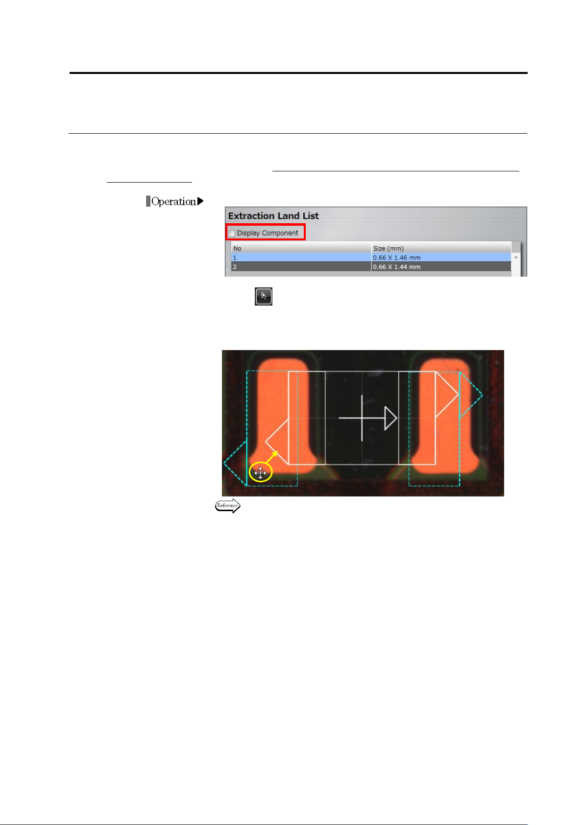
・ Adjust the Land Position
Align the auto-extracted land windows to the corresponding positions on the bare PCB image.
This operation is not usually required. Perform it only when the PCB is a leveler board or a raw
PCB is unavailable.
1.
Deselect the [Display Component] checkbox.
2.
Select (Select Window) in the Image Operation tool bar, if it is not
selected.
3.
Drag the land windows to the land positions on the bare PCB image
(area colored in orange on the image below).
Refer to "2.1.3 Image Display Area Operation" for the image display
area operation.
4.
Click [Next] to proceed to the Electrode Group Setting screen.
Operation
Drag