Omron V-TS Teaching Manual.pdf.pdf - 第32页
2.1 Bas ics of Teaching 2-5 Inspection Program Status Th e st at u s o f th e i n sp ec ti on p r og ra m i s up da te d in a cc or da n ce w it h t h e p ro g ra m cr ea ti on pr og re ss . <New> Refers to the s…
Chapter 2 Inspection Programming
2-4
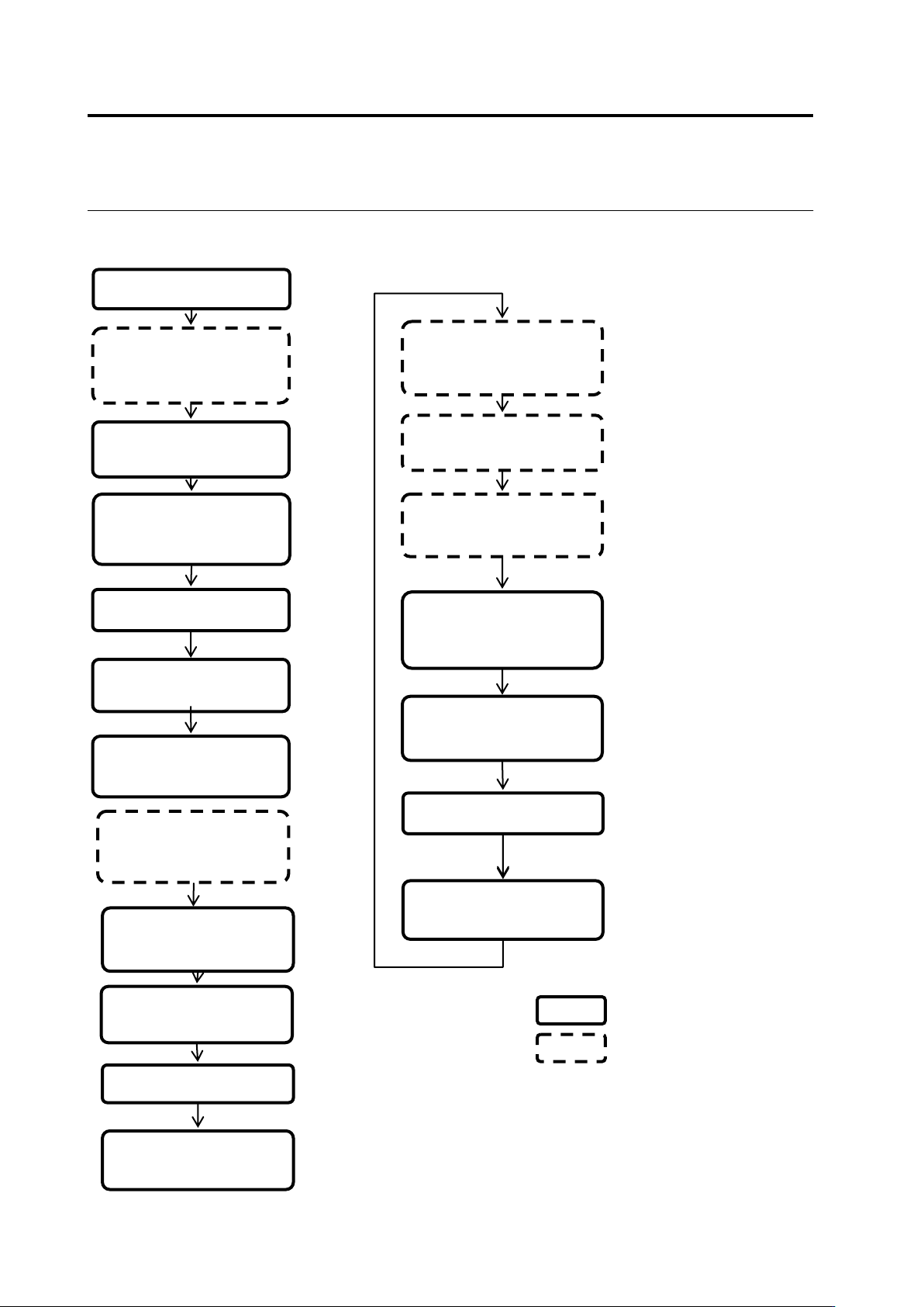
Teaching Flow
1) New creation
Shoot raw PCBs and
inspection PCBs using
the PCB inspection
system
4) Set up the criterion
5) Set up PCB and
component block ID
2) Register inspection
Set up destination
3) Register the
component number
model
■ Inspection program creation flow
14) Release the
inspection program
Inspect the PCB using
the PCB inspection
system
Classify OK and NG
products using v-CA
Monitor and analyze the
result using Q-upNavi
12) Correct the
inspection program
13) Confirm the result
■ Inspection program tuning flow
v-TS
Other than v-TS
6) Adjust and save the
inspection program
10) Release the
inspection program
7) Confirm the PCB
test result
9) Confirm the result
Inspect the PCB in
adjustment mode using
the PCB inspection
system
8) Correct the
inspection program
11) Confirm inspection
NG images captured
during mass-production

2.1 Basics of Teaching
2-5
Inspection Program Status
The status of the inspection program is updated in accordance with the program creation progress.
<New>
Refers to the state after the creation of a new inspection program starts and before the
bare and inspection PCB images are captured.
See 1) in the flow above.
<Teaching>
Refers to the state where the PCB images are captured and before the inspection program
is released.
See 2) to 5) in the flow above.
An inspection programs in the teaching status cannot be used on the PCB inspection
system.
PCBs can be captured by the PCB inspection system.
<Adjusting>
Refers to the state where the inspection program is saved in adjustment and before the
program is released.
See 6) to 9) in the flow above.
An inspection program in the adjusting status can be used to obtain adjusted images on
the PCB inspection system.
PCBs cannot be inspected by the PCB inspection system.
<Operating>
Refers to the state after the inspection program is released.
See 11) to 14) in the flow above.
An inspection programs in the Operating status can be used on the PCB inspection
system.
In addition, even if the latest status of the inspection program is changed by saving it
after releasing or adjustment, the inspection program when it was released can be
inspected by the PCB inspection system continuously.
Chapter 2 Inspection Programming
2-6
Component Number
Inspection criteria and inspection windows must be specified by the unit of component number
in teaching.
A component number after teaching is registered in the library for reuse when additional
inspection programs are created.
Component Number Library
A library is provided for managing component number information. Component number
information is saved in the component number library. The inspection program obtains
component number information by referring to the component number library. The inspection
program itself does not have component number information. More than one component
number libraries can be created, and identified by the library number and library name. If the
system of component number names is different from each other among the customers,
manage the component numbers using separate component libraries.
Inspection Windows
Inspection windows can be categorized into several types including Inspection Region Window,
Component Body Window, Land Window and Electrode Window. Windows are positioned over
the PCB image, and inspection criteria is specified for each window.
Each window is displayed in a different color as shown below:
・White…Inspection Region Window, Component Body Window or Electrode Window
・Yellow…Land Window
・Light Blue…Selected window
In addition, there are windows with no inspection criterion in addition to the windows above,
displayed in the following colors, respectively:
- White: Component Body Plus Window, Lifted Component Window
- Gray: Component Body Minus Window, and Excluded Window (component number)
- Light green: Component Body Minus Window, Excluded Window (PCB)
- Yellow: Wrong Polarity/Height Reference Point Window
- Light Blue: Wrong Polarity/Height Measurement Point Window
Refer to the Inspection Logic Manual, "1.4 Component Types and Individual Windows" for the window
positioning procedure.
Model Calculation
The characteristic parameters used in inspection logics are automatically extracted based on
the windows and model images specified for individual component numbers. The extracted
characteristic parameters are registered in the library.
Refer to the Inspection Logic Manual, P1-2 "1.2 Inspection Parameter" for details on characteristic
parameters.
Component Angle
This system uses the symbols composed of "+" (representing the center of the component) and
"△" (direction) to show the component angles.