Omron V-TS Teaching Manual.pdf.pdf - 第302页
Appendix 7. Positio n Correction/Extractio n a- 25 4) Set the parameters if not se t. Details of the procedure to adjus t component extract ion using characteristic para meters are as follows: The com ponent extraction f…
Appendix 7. Position Correction/Extraction
a-24
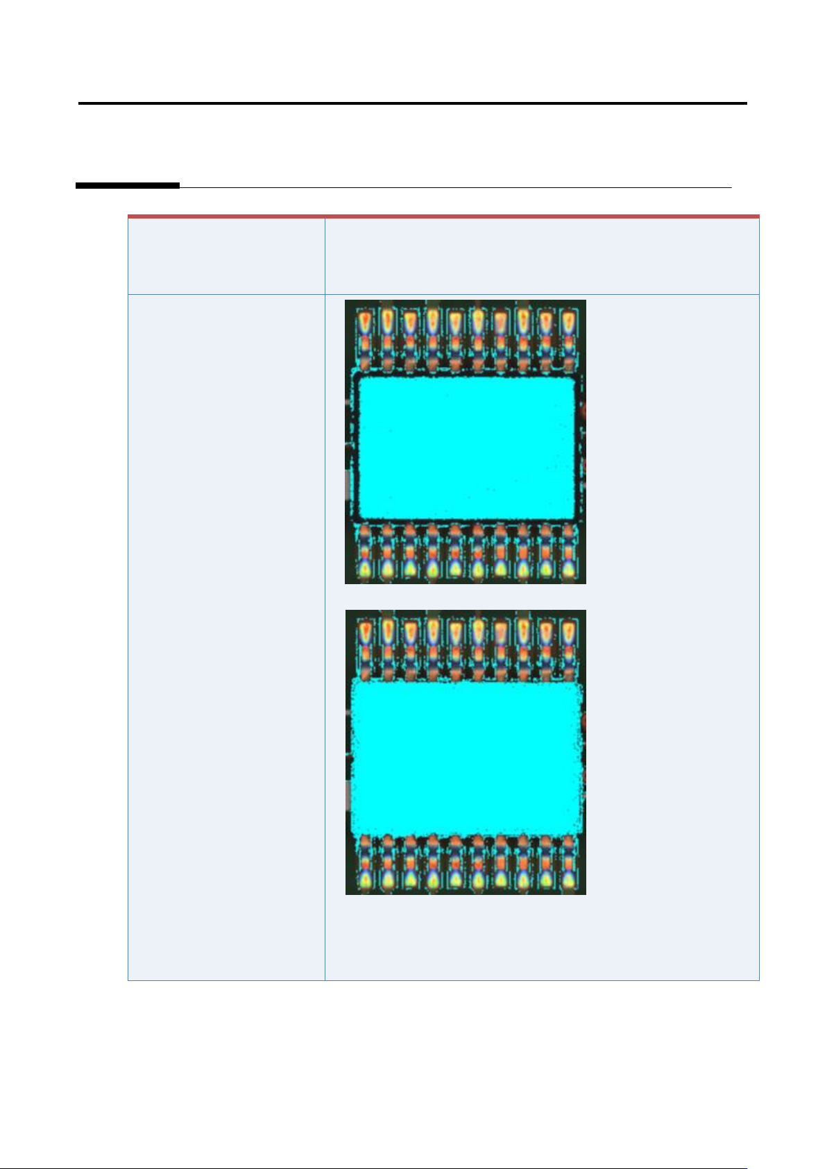
If the component has a tilted
side
Characteristic parameters
are not set appropriately.
(The component body color
and electrode color are not
being set sufficiently.)
1) Set the parameters if not set.
2) Select “Inspection Criteria” - “Extract Electrode Tip,” and click
the [Model Editing] button.
3) Confirm if the electrode color is being set.
Appendix 7. Position Correction/Extraction
a-25
4) Set the parameters if not set.
Details of the procedure to adjust component extraction using characteristic parameters are as follows:
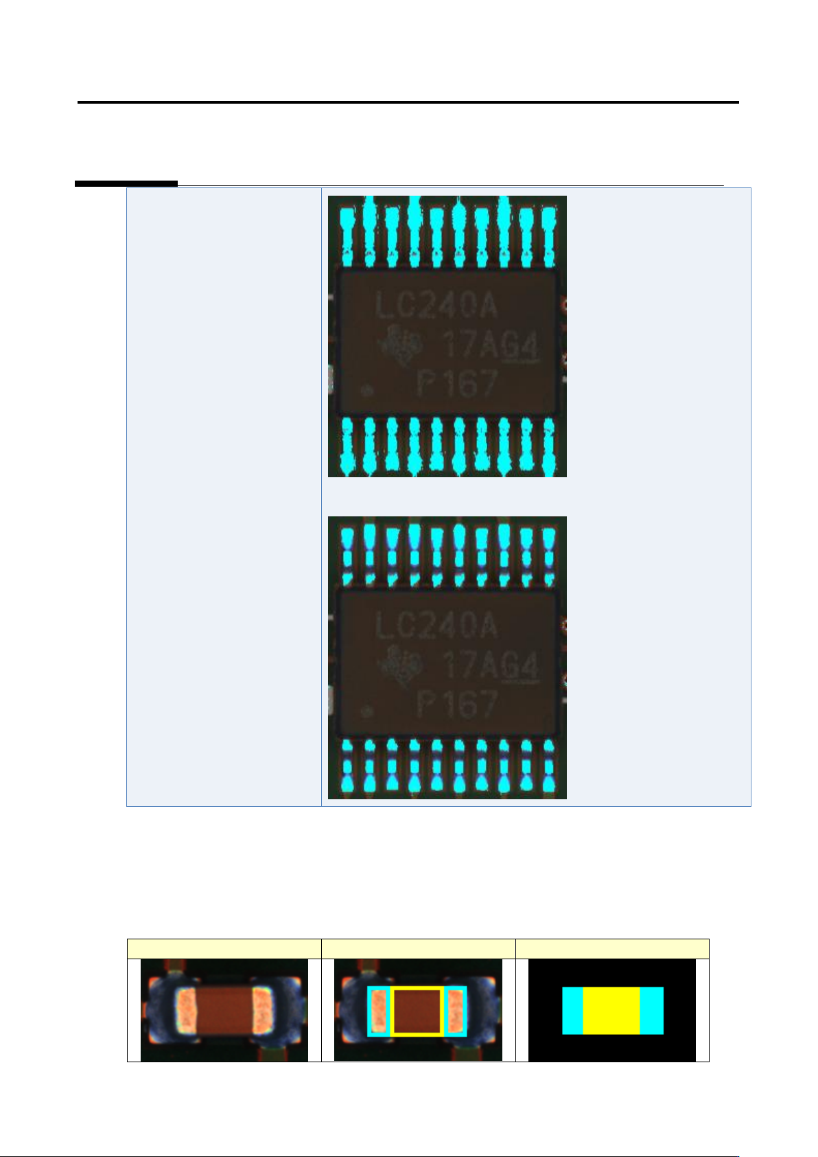
The component extraction function extracts something similar to the component by template (model)
matching. The component extraction model is created based on the window setting like the figure below.
Inspection image
Window setting
Component extraction model
Appendix 7. Position Correction/Extraction
a-26
Inspection image
Window setting
Component extraction model
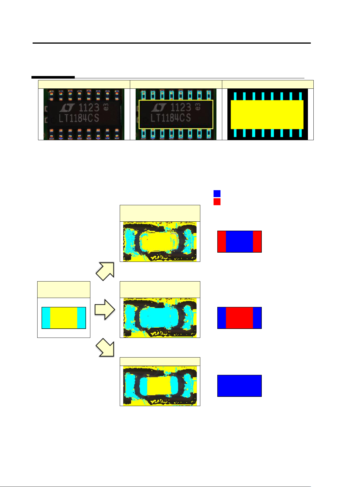
For stable component extraction, the characteristic parameters need to be configured so that the rate of
matching between the component extraction model and binarized inspection image becomes higher. To
close to the 100% matching rate, the component and electrode need to be binarized with each
characteristic parameter.
Matched image
Unmatched image
Electrode is binarized with
the component color
Matching rate
drops on
electrode area.
Component
extraction model
Component is binarized with
the electrode color
Matching rate
drops on
component
area.
Good binarization
Matching rate
does not drop.