Omron V-TS Teaching Manual.pdf.pdf - 第277页
Chapter 3 Man agement Menu 3- 22 3. T o create a new set of stage moving configurations, c lick [Create New]. A set of stage moving configurations is c reated and ad ded to the list. It is created as a set name of "…
3.4 Managing Component Number Libraries
3-21
3.5 Setting Model Codes
Model codes are set for each inspection program in this section.
You can manage model code settings for each inspection program as a set and specify any
set of model codes as a stage moving condition for a host link connection on a system.
For how to set an automatic stage moving condition for a host link connection, see Operation Manual
of inspection machine, "4.8.2 Upper Link Setting".
1.
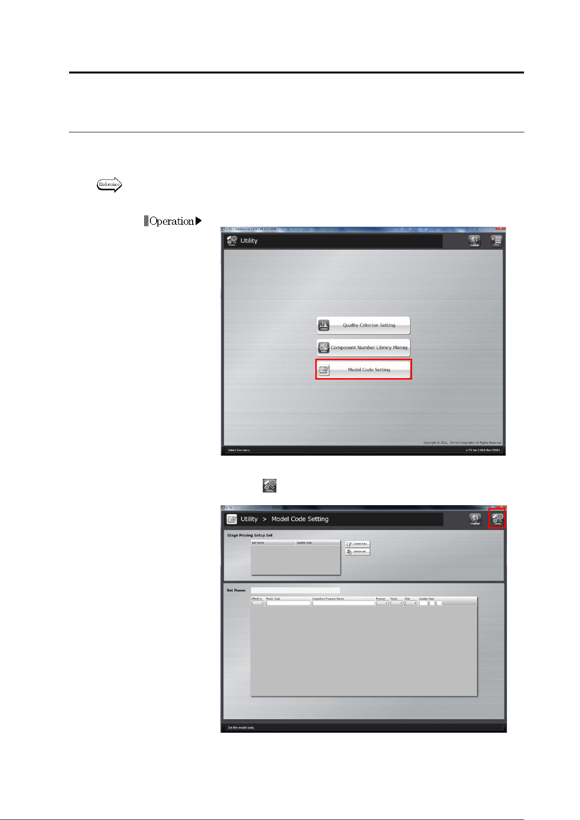
Click [Mode Code Setting] on the utility menu.
2.
The model code setup screen will appear.
Click the button on the top-right screen to return to theutility
menu.
Chapter 3 Management Menu
3-22
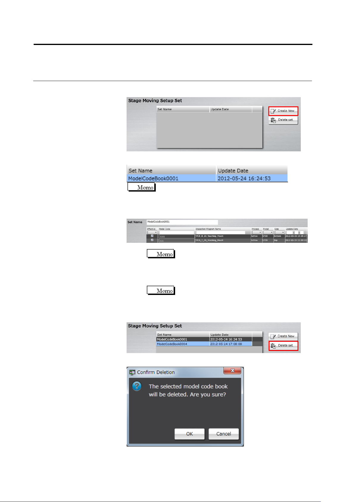
3.
To create a new set of stage moving configurations, click [Create
New].
A set of stage moving configurations is created and added to the list.
It is created as a set name of "ModelCodeBook + 4-digit serial
number” as a default.
4.
Click a set of stage moving configurations from the list you want to
configure, and specify a model code for each inspection program.
1. Click the text box of [Set Name] and enter a set name.
You cannot enter an existing set name.
2. Select the enabling check box of an inspection program for
which a model code is configured to enable.
3. Click the model code field of the inspection program you
enabled, and enter a model code.
You cannot edit a model code for an inspection
program that is not enabled.
5.
When you want to delete Stage Moving Setup Set, click Stage
Moving Setup Set from the list and select [Delete set].
The deletion confirmation dialog appears. Click [OK].

a-1
Appendix Teaching Flow
Appendix Teaching Flow ....................................................................... 1
Appendix 1. Initial Programming ........................................................... 2
Appendix 2. Initial Adjustment ............................................................... 6
Appendix 3. Mass Production Adjustment (false call minimization) ..... 8
Appendix 4. Mass Production Adjustment (false call zero) ................ 10
Appendix 5. Real Fault Registration Procedure ................................. 11
Appendix 6. Selection of Optimization Items ...................................... 13
Appendix 7. Position Correction/Extraction ........................................ 14
Appendix 8. Height Information Setting .............................................. 37
Appendix 9. Land Inspection Adjustment Procedure .......................... 40
Appendix 10. Inspection Criteria Setting ............................................. 61
Appendix 11. PCB Test Result Output Format .................................... 63