Omron V-TS Teaching Manual.pdf.pdf - 第299页
Appendix 7. Positio n Correction/Extractio n a- 22 In the two figures o n the left, the values are within the inspection cr iteria, and in the t wo figures on the right, the values are n ot within the inspec tion criteri…
Appendix 7. Position Correction/Extraction
a-21
4. Inspection items adjustable with characteristic parameters
When false call or detection failure occurs and the characteristic parameters regarding the inspection
items can be adjusted, characteristic parameters should be adjusted.
1) For a false call, adjust that the measurement value of the good component is within the inspection
criteria.
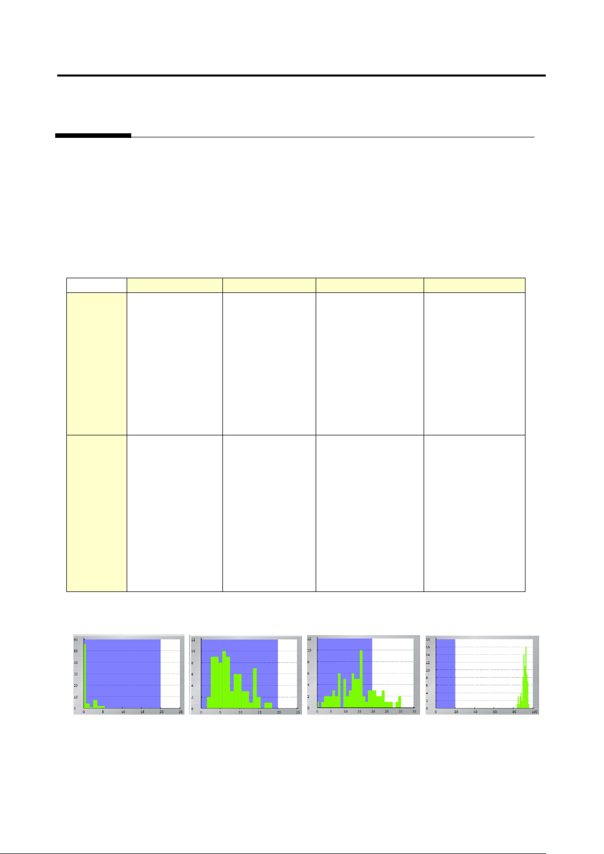
2) For a detection failure, adjust that the good and fault can be separated using the histogram.
* Adjust the good component so that the value is within the inspection criteria, as shown in (1).
Component
Electrode
Land
Inspection range
Adjustable
Missing
component
Component
difference
Polarity difference
Upside down
component
X position gap
Y position gap
Component skew
Side overhang
End overhang
End overlap
Electrode length
Electrode area
Side bend
Electrode height
(oblique)
Exposed land
Land error
Foreign object (land)
Exposed land
(oblique)
Solder ball
Solder bridging
Foreign object
Solder ball (oblique)
Solder bridging
(oblique)
Not
adjustable
None
Exposed
electrode tip
(oblique)
Electrode color
deviation
Exposed
electrode tip
(oblique)
Electrode color
deviation
(oblique)
Fillet inspection (all)
None
In the two figures on the left, the values are within the inspection criteria, and in the two figures on the
right, the values are not within the inspection criteria.
Appendix 7. Position Correction/Extraction
a-22
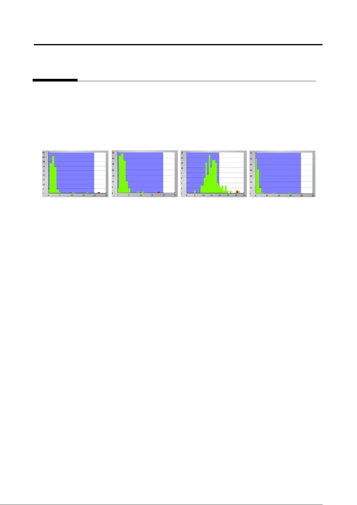
In the two figures on the left, the values are within the inspection criteria, and in the two figures on the
right, the values are not within the inspection criteria. “The good and fault can be separated” means all
the good components are within the inspection criteria, and faulty components are not. Even if faulty
components are inside the inspection criteria, there is no problem if the interval between the measured
value of the good component closest to the fault and the measured value of the fault is as follows:
Unit of %: 5%
Unit of angle: 1
Unit of mm: 0.05 mm
Appendix 7. Position Correction/Extraction
a-23
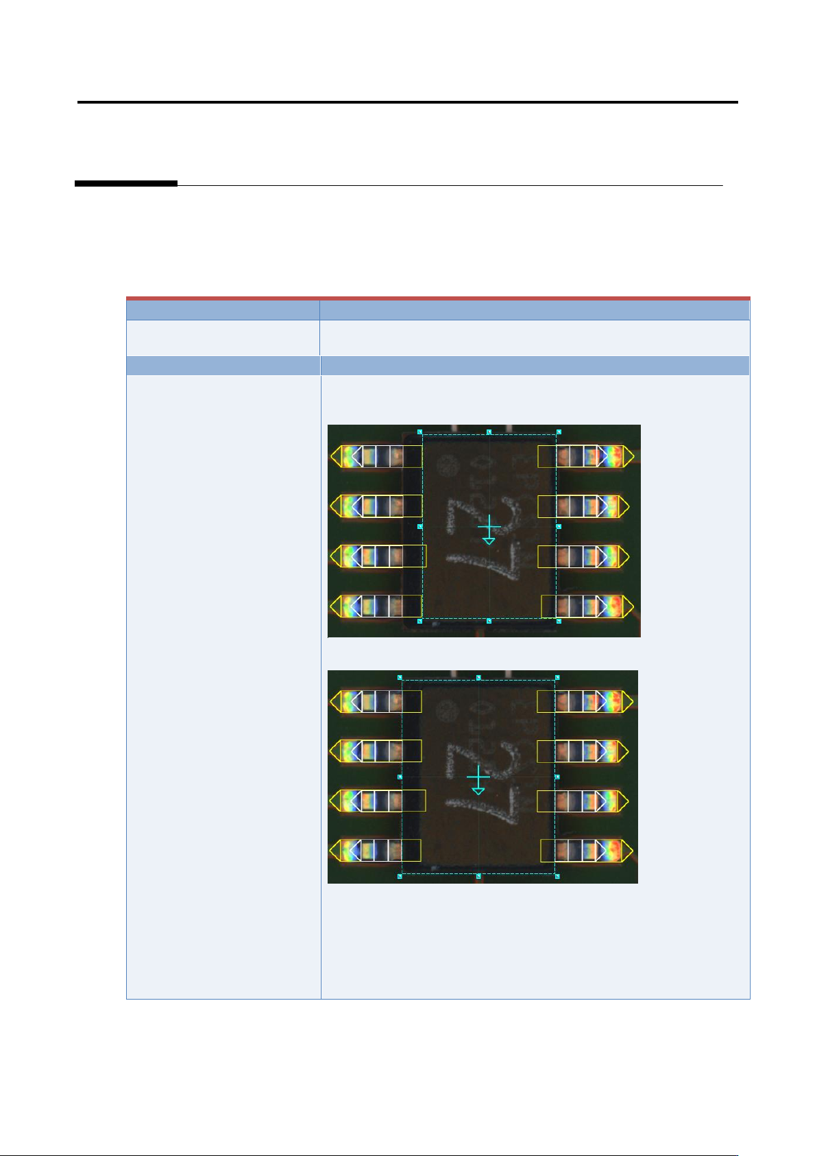
5. Component extraction
A component is extracted in the inspection range window, the positions of the component body window
and electrode window are corrected and specified as the reference positions for the component body
inspection and electrode inspection.
Inspection result
Component image (PCB test)
Cause
Confirmation and repair method
The component body window
and electrode window are not
sized appropriately.
1) Move to the “Inspection Registration” tab.
2) Confirm that the component body window has an appropriate
size.
3) If not appropriate, change the size/position of the component
body window, and click the [Next] button.
4) Click the [Next] button.
5) Click the [Next] button.
6) Confirm that the electrode window has a size consistent with
the image.
7) If not consistent, change the electrode window’s size/position.