Omron V-TS Teaching Manual.pdf.pdf - 第223页
Chapter 2 Insp ection Progr amming 2- 196 ⑧ Extension range setting tool : Specify an extension r ange of the pixel sel ected by the pen or eraser tool us ing the slide bar. T he extension range ca n be specif ied in a r…
2.16 Managing PCB Images
2-195
■ Reference level model editing tool - Description on the screen functions
This section describes each function displayed in the right pane of the screen of the
reference level model editing tool.
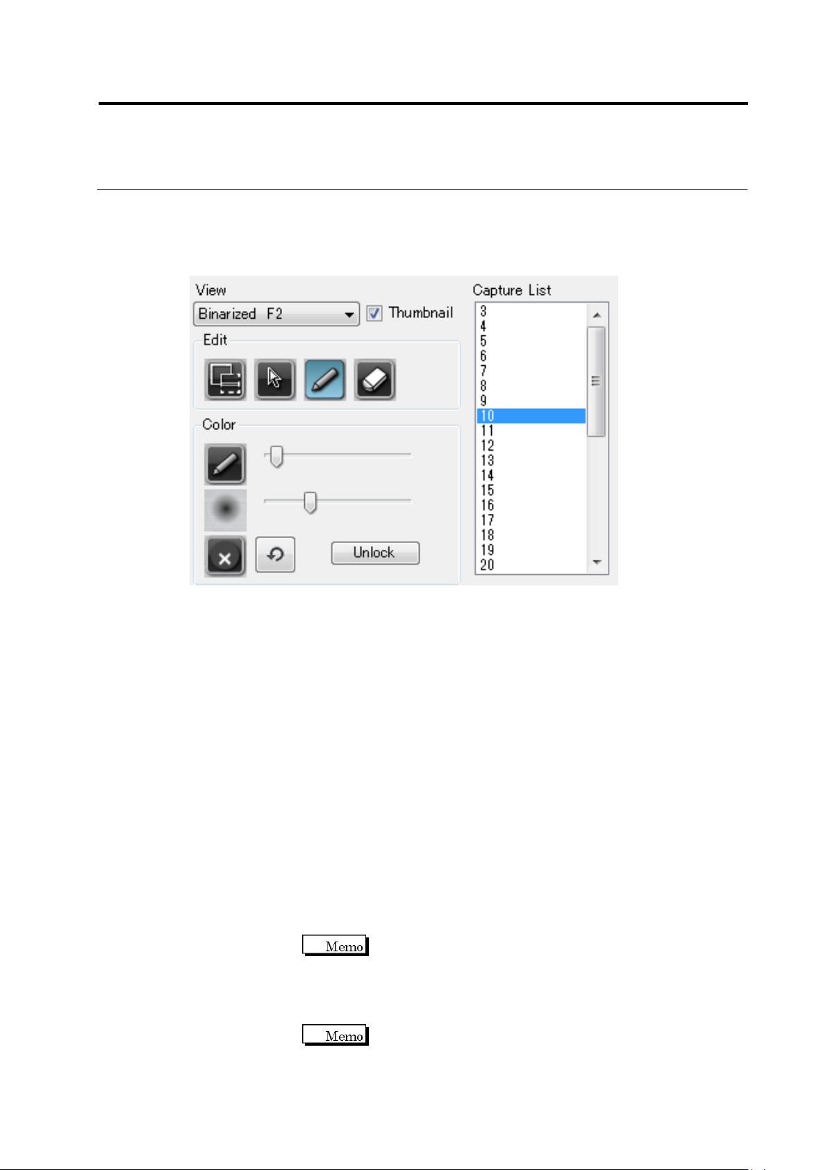
① View : Image selecting combo box.
Source F1 : Displays the RGB image of the inspection FOV edited.
Binarized F2 : Displays the image binarized from an RGB image by the color table.
Height F3 : Displays the height image of the base plane.
② Thumbnail button : Use this button to display the thumbnail of an inspection FOV
image. The FOV image can be displayed as a thumbnail by turning
ON this button, and in the original FOV size by turning OFF this
button.
③ Inspection FOV list : Displays the FOV of the inspection program.
④ Add mask button : A mask can be added by dragging a target area.
⑤ Select button : Use this button to select various areas on the screen, such as a
component, mask, or base plane.
⑥ Pen tool : By clicking a pixel to be extracted on the PCB, the color of the
pixel is added to the color table. Pen’s thickness can be specified
using the slide bar.
Pen’s thickness can be specified in a range of 1-21 pixels.
⑦ Eraser too : By clicking a pixel to be extracted from the PCB (area colored in
cyan blue), the color of the pixel is deleted from the color table.
Eraser’s thickness can be specified using the slide bar.
Eraser’s thickness can be specified in a range of 1-21
pixels.
①
②
③
④
⑤
⑥
⑧
⑨
⑩
⑦
⑪
Chapter 2 Inspection Programming
2-196
⑧ Extension range setting tool : Specify an extension range of the pixel selected by the
pen or eraser tool using the slide bar.
The extension range can be specified in a range of 0-20.
⑨ Clear button : Deletes all color settings from the color table.
⑩ Undo button : Cancels the edited data of the color table.
⑪ Unlock button : Unlocks and returns the settings of reference level model to the
initial condition.
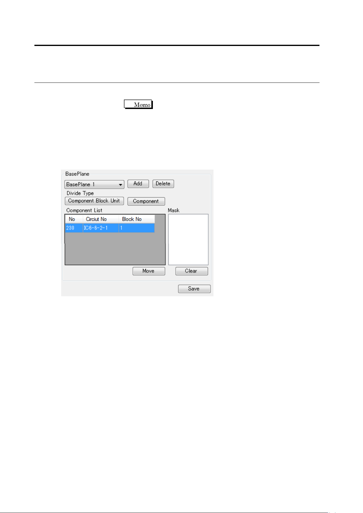
⑫ Base plane displaying combo box : Displays added base planes. BasePlane 0 is
the original base plane, and the others are the added base planes.
⑬ Base plane adding button : Use this button when selecting an area or a
component on the base plane partitioned to add base planes.
⑭ Base plane deleting button : Deletes the selected base plane.
⑮ Base plane per-block partitioning setup button : When component block unit is
already set up by the inspection program, if this button is clicked,
the base plane is partitioned on a component block unit basis in the
overall FOV.
⑯ Base plane per-component partitioning setup button : Partitions the base plane
on a component basis in the overall FOV.
⑰ Component list : Displays the components belonging to the base plane selected by
[BasePlane] in the selected inspection FOV.
⑱ Mask list : Displays the masks of the base plane selected by [BasePlane] in
the selected inspection FOV.
⑫
⑬
⑭
⑮
⑯
⑰
⑱
⑲
⑳
㉑
2.16 Managing PCB Images
2-197
⑲ Component transfer button : Moves the components registered in base plane A to
base plane B.
⑳ Delete all masks button : Deletes all masks.
To delete a mask, select the mask on the Mask list, and
click the [Delete] button.
㉑ Save button : Saves the reference level model which has been edited
completely.
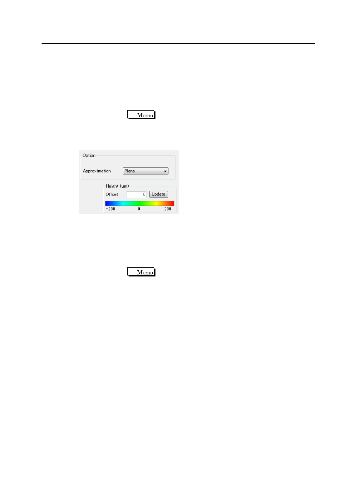
㉒ Base plane approximation method selecting combo box : Specify a method to
approximate the base plane as plane approximation (Plane) or
curved face approximation (Curve2).
㉓ Change offset button : By entering a numerical number and clicking the [Update] button,
the offset value can be changed.
The offset value is zero by default.
㉒
㉓