Omron V-TS Teaching Manual.pdf.pdf - 第276页
3.4 Managing Com ponent Num ber Libraries 3- 21 3.5 Setting Model Codes Model codes are set for each i nspection program in this section. Y ou can manag e model code settings for each insp ection progra m as a set and sp…
Chapter 3 Management Menu
3-20
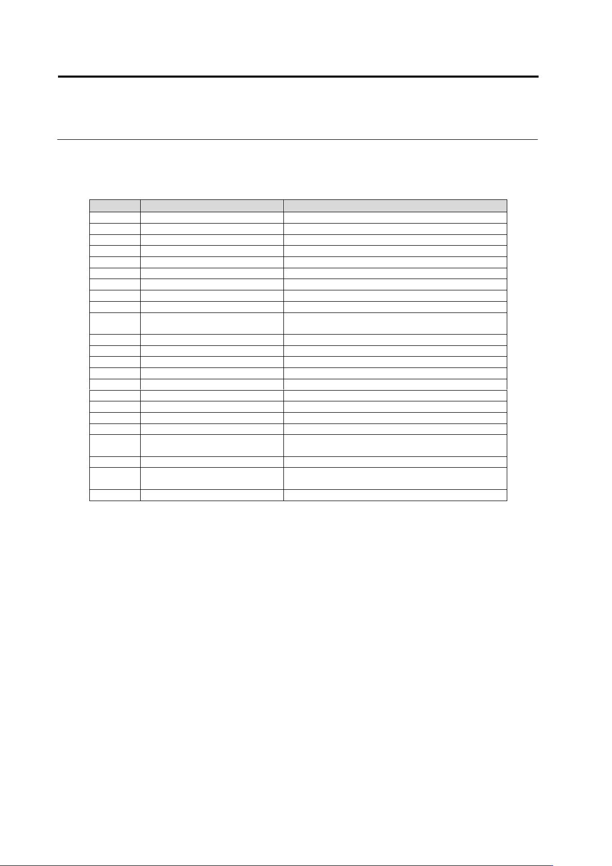
Output format of a list of the component numbers used by inspection
programs
Column
Item
Description
1
CompanyId
ID of component No. library
2
Model
Model name of inspection program
3
Component No. group ID
ID of component No. group
4
Component No. group revision
Revision of component No. group
5
Component No. group name
Name of component No. group
6
Component No. ID
ID of component No.
7
Component No. revision
Revision of component No.
8
Component No. name
Name of component No.
9
Component type
Type of component
10
Update date and time
(component No.)
Date and time of update of component No.
11
Inspection logic version
Version of inspection logic used by component No
12
PJ-ID
System ID of PCB
13
PG-ID
System ID of inspection program
14
PJ-Revision
System revision of PCB
15
PG-Revision
System revision of inspection program
16
PCB name
Name of PCB
17
Inspection program name
Name of inspection program
18
Front/back
Front/back of PCB inspected by inspection program
19
Process
Name of inspection process
20
Update date and time
(inspection program)
Date and time of update of inspection program
21
Status
Status of inspection program
22
Component No. revision
(inspection program)
Revision of component No. referred by inspection
program
23
Comment
Content of comment
3.4 Managing Component Number Libraries
3-21
3.5 Setting Model Codes
Model codes are set for each inspection program in this section.
You can manage model code settings for each inspection program as a set and specify any
set of model codes as a stage moving condition for a host link connection on a system.
For how to set an automatic stage moving condition for a host link connection, see Operation Manual
of inspection machine, "4.8.2 Upper Link Setting".
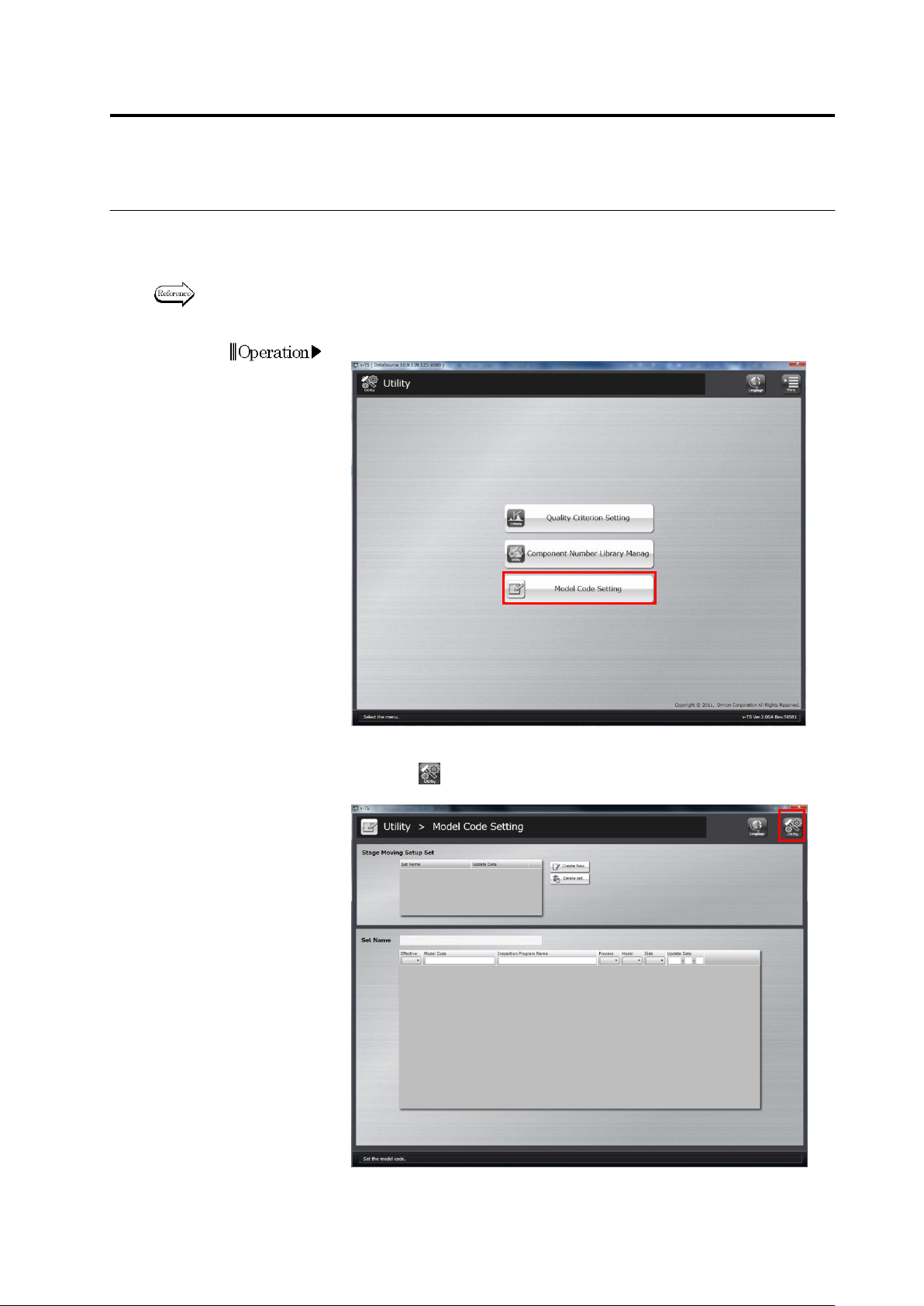
1.
Click [Mode Code Setting] on the utility menu.
2.
The model code setup screen will appear.
Click the button on the top-right screen to return to theutility
menu.
Chapter 3 Management Menu
3-22
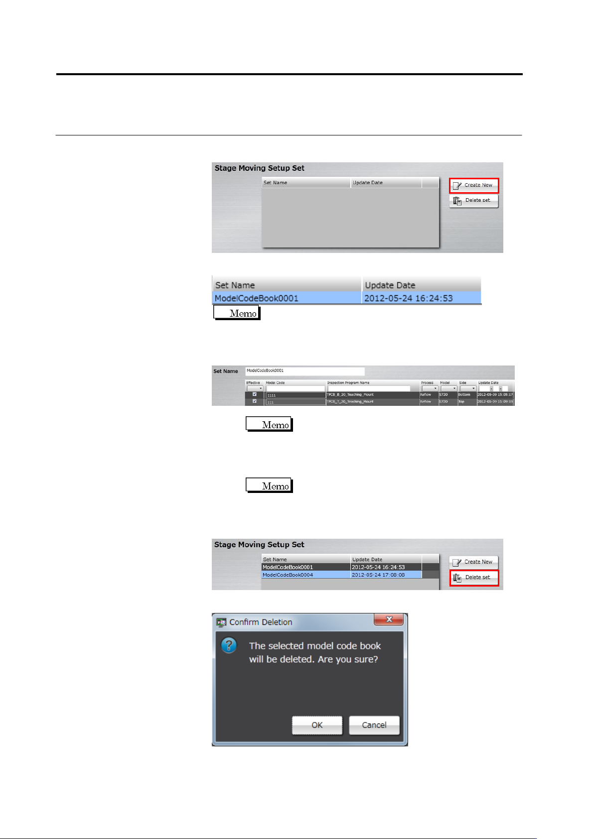
3.
To create a new set of stage moving configurations, click [Create
New].
A set of stage moving configurations is created and added to the list.
It is created as a set name of "ModelCodeBook + 4-digit serial
number” as a default.
4.
Click a set of stage moving configurations from the list you want to
configure, and specify a model code for each inspection program.
1. Click the text box of [Set Name] and enter a set name.
You cannot enter an existing set name.
2. Select the enabling check box of an inspection program for
which a model code is configured to enable.
3. Click the model code field of the inspection program you
enabled, and enter a model code.
You cannot edit a model code for an inspection
program that is not enabled.
5.
When you want to delete Stage Moving Setup Set, click Stage
Moving Setup Set from the list and select [Delete set].
The deletion confirmation dialog appears. Click [OK].