Omron V-TS Teaching Manual.pdf.pdf - 第247页
Chapter 2 Insp ection Progr amming 2- 220 2.18.6 Copying an Insp ection Program 1. Select the inspection pr ogram to copy in the Select PCB scr een and click [Cop y]. The inspection program is copied and cop ied program …
2.17 Mass-Produced PCB Image
2-219
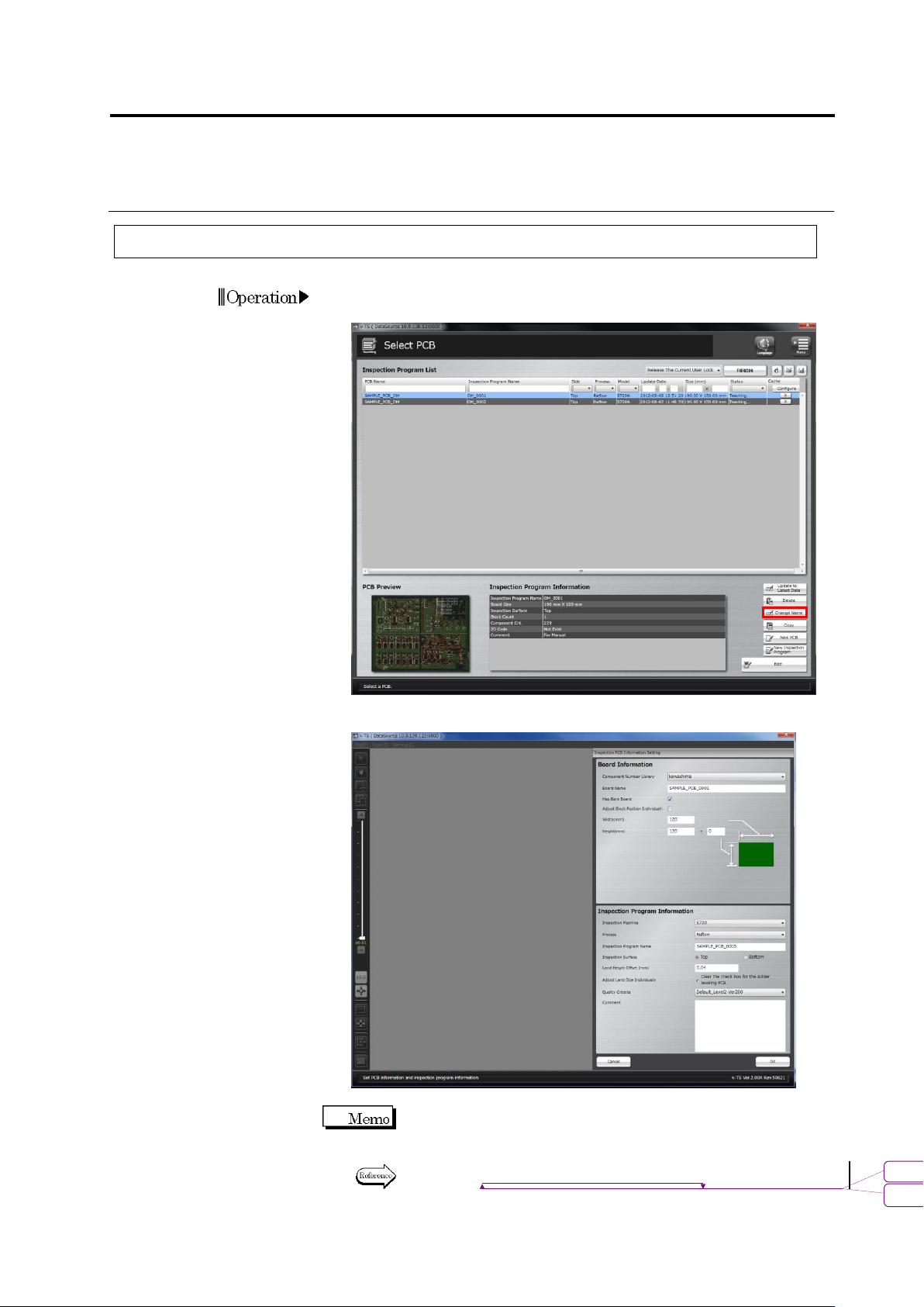
2.18.5 Renaming an Inspection Program
1.
Select the inspection program to rename in the Select PCB screen
and click [Change Name].
2.
The Inspection PCB Information Setting screen is displayed.
Change the name of the program and click [OK].
Only the PCB name, presence of bare board, adjust block position
individually, inspection program name, inspection surface, auto size
adjustment for each land and comment can be edited.
Refer to "2.2 Creating a New Inspection Program" for the details on
individual input items.
Operation
書式変更: フォント : 9 pt
削除
: Creating a New Inspection Program
Chapter 2 Inspection Programming
2-220
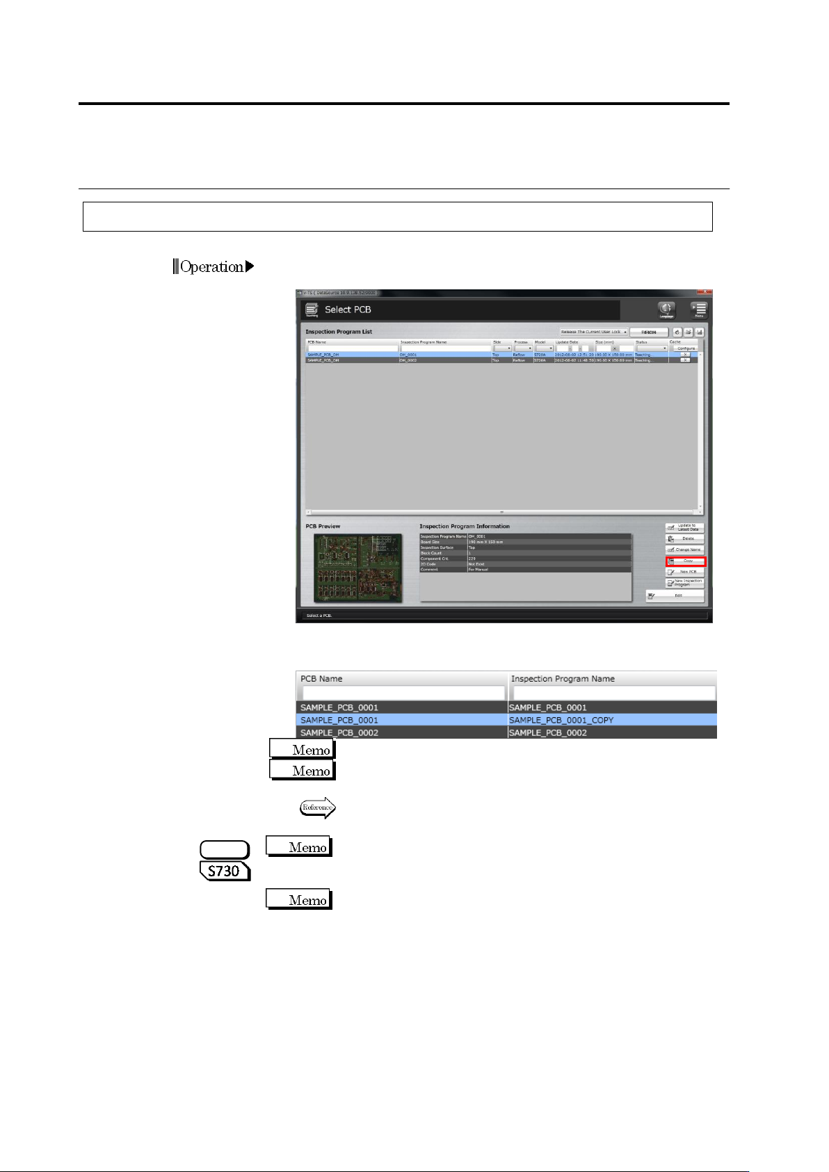
2.18.6 Copying an Inspection Program
1.
Select the inspection program to copy in the Select PCB screen
and click [Copy].
The inspection program is copied and copied program is displayed
in the Inspection Program List.
Copying an inspection program requires a certain amount of time.
The copied program is named with the default name "The name of
the original inspection program_COPY".
To rename the program name, refer to "2.18.5 Renaming an
Inspection Program".
If an inspection program with oblique images is copied, oblique
images are deleted. The program can be used as an inspection PCB
only including direct view images.
Since oblique images cannot be diverted depending on the
component location, they are deleted when an inspection program is
copied.
Operation
S720A
2.17 Mass-Produced PCB Image
2-221
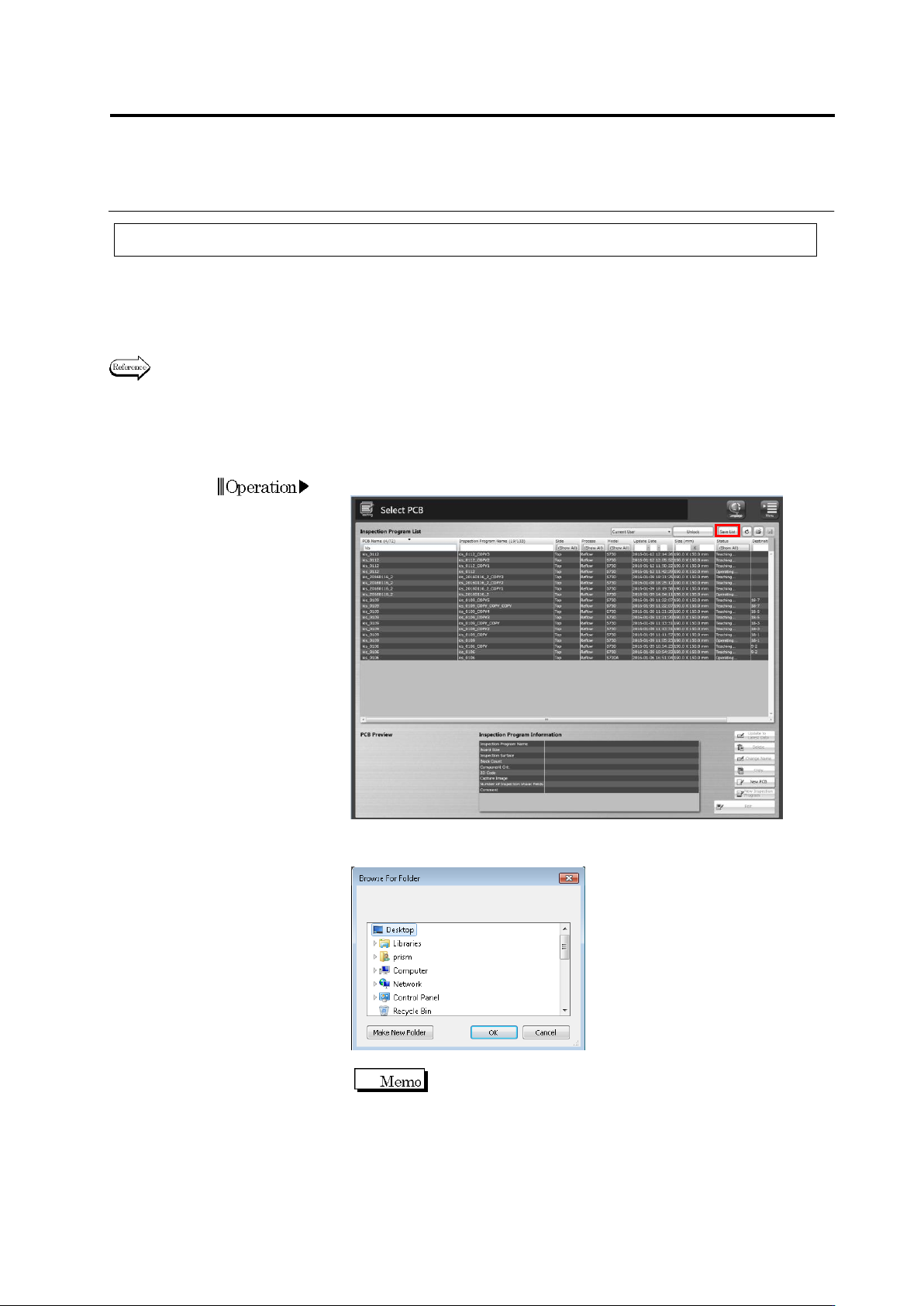
2.18.7 Outputting Content of Inspection Program List
This function outputs to a CSV file the content of an inspection program list, such as information
on inspection programs, progress of the creation work of them, the number of images belonging
to each inspection program, the number of inspection programs, the number of destinations, or
version of the logic being used.
When outputting a list of the component numbers used by inspection programs, refer to Section
3.4.3 “Outputting List of Component Numbers Used by Inspection Programs.”
This section describes the procedure to output the content of an inspection program list.
2.
Click the [Save List] button on the Select PCB screen.
3.
A dialog to browse folders is displayed.
Specify a folder to save the file, and click [OK].
The default file name is “(Date and
Time)InspectionProgram.csv.”