Omron V-TS Teaching Manual.pdf.pdf - 第251页
Chapter 2 Insp ection Progr amming 2- 224 2.18.8 Verifying Inspection P rogram Data Data integrity of an insp ection program is verified to prevent tra nsmiss ion of illegal data to be sent to an inspection m achine . Sh…
2.18 Inspection Program Maintenance
2-223
Inspection program list output format
Column
Item
Output data
1
PCB name
Name of PCB
2
Inspection program name
Name of inspection program
3
Front/back
Front/back of PCB inspected by inspection program
4
Process
Name of inspection process
5
Model
Model name corresponding to inspection program
6
Update date and time
Date and time of update
7
Size (mm)
PCB size: horizontal size x vertical size (mm)
8
Status
Status of inspection program
9
Save FOV image(Inside information)
Setting ON/OFF of FOV image saving function for
inspection
10
Destination
Presence/absence of destination
11
No. of component block units
No. of component block units
12
No. of components
No. of components
13
2D code
Presence/absence of 2D codes
14
No. of shot images (raw PCB)
No. of shot images of raw PCB
15
No. of shot 3D images (raw PCB)
No. of shot 3D images of raw PCB
16
No. of shot images (reflow)
No. of shot reflow images
17
No. of shot images (reflow 3D)
No. of shot reflow 3D images
18
No. of shot images (reflow 3D full)
No. of shot reflow 3D full images
19
No. of shot images (adjustment)
No. of shot adjustment images
20
No. of shot images (adjustment,
oblique)
No. of shot oblique adjustment images
21
No. of shot images (adjustment, 3D)
No. of shot adjustment 3D images
22
No. of shot images (adjustment, 3D,
oblique)
No. of shot oblique adjustment 3D images
23
No. of inspection FOV
No. of inspection FOV
24
No. of inspection FOV (oblique)
No. of oblique inspection FOV
25
Change release to teaching
Presence/absence of change
26
Comment
Content of comment
27
PJ-ID
System ID of PCB
28
PG-ID
System ID of inspection program
29
PJ-Revision
System revision of PCB
30
PG-Revision
System revision of inspection program
31
CompanyId
ID of component No. library
Chapter 2 Inspection Programming
2-224
2.18.8 Verifying Inspection Program Data
Data integrity of an inspection program is verified to prevent transmission of illegal data to be sent
to an inspection machine.
Shown below are details of the primary data verification.
Verification is done if an inspection program can be used on an inspection machine or not.
Target Data
Checking Details
Inspection
Program
Position Correction Mark
2D Code
Bad Mark
Component Block Unit Edge
Window positions, count, and sizes must be proper
Inspection criteria must be proper
Must have a model
Must have a color
Must belong to a PCB or a component block unit
Component Block Unit
Must have a circuit
The No. of circuits of component block units must be the same
Image Capturing Route
A mark or circuit must have a view
Must have a multi-screen component view
Must have a single-screen component view
Base Plane Model
Must have a base plane model corresponding to a view
Pattern Position Correction Model
Must have a pattern position correction model corresponding to
a view
Characteristic Parameter
Must have a model
Must have a color
Circuit
Inspection Range Window
Inspection Range (Oblique) Window
Component Window
Electrode Window
Land window
Window positions, count, and sizes must be proper
Must have a pair window
Must have the same angle as that of pair window
Individual Setting
Sub-window position and size must be proper
Inspection criteria must be proper
Oblique View Setting
Secondary Reflection
Customer-Specific
Must satisfy valid conditions
Component
Number
Component Type
Item No. Name
Must have been configured
Progress Signal
Window registration must have been done
Must have a characteristic parameter
Component Window
Electrode Group
Electrode Window
Land window
Sub-Window
Window positions, count, sizes, and angles must be proper
Must have a pair window
Must have the same angle as that of pair window
Inspection criteria must be proper
Height Information
A height of 0.1mm or higher must have been set
A light intensity level must have been set
A stripe size must have been set
Characteristic Parameter
Must have a model
Must have a mask model
Must have a color
Component
Number
Group
Component Number List
Must have a component number list
Characteristic Parameter
Must have a color
2.18 Inspection Program Maintenance
2-225
Data Verification
Data verification is automatically done in the following timings:
- When data is updated to the latest
- When an inspection program is released
* Data verification upon release aims at component numbers and component number groups that
have acquired locking
(All inspection programs and circuits will be verified)
This section describes data verification which is automatically executed.
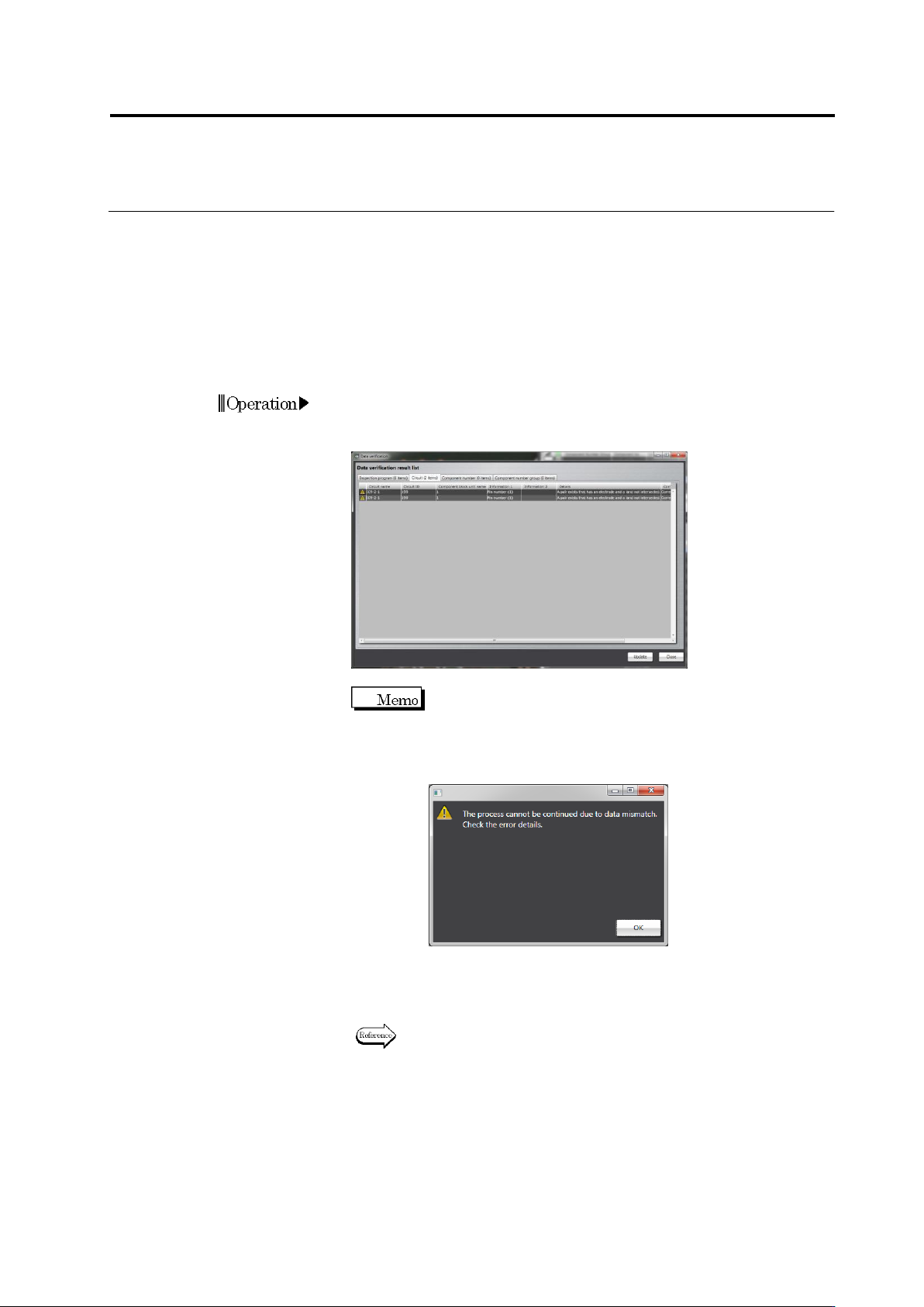
1.
Data verification is automatically done in given timings
.
If an error is
detected in a data verification result, the data verification result list
appears.
You can continue the processing without recovering data
by pressing the [Continue Processing] button. If
mismatching occurred in data required to proceed,
however, a warning screen appears, preventing to
proceed.
2.
Recover the data based on the recovery steps
.
If the result error
disappears, the data verification list does not appear and the
process is continued.
For the recovering method, refer to “Data Recovery Flow” of Section
2.18.8 Verifying Inspection Program Data.”