Omron V-TS Teaching Manual.pdf.pdf - 第327页
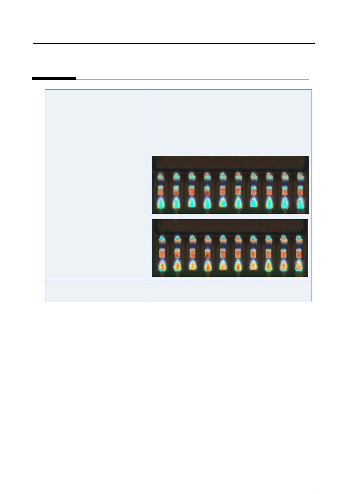
Appendix 9. Land Insp ection Adjustm ent Procedure a- 50 Inspection item 6. Fillet - Side connection length Based on the solder c olor detected in the land windo w , inspect if the fillet conn ection length to the electr…
Appendix 9. Land Inspection Adjustment Procedure
a-49
The fillet excluded color is not set
appropriately.
1) Move to the “Criteria Setting” tab.
2) Select “Inspection Criteria” - “Connection Area Height
(Maximum Height)”, and click the [Model Editing] button.
3) Edit characteristic parameters using the color table editing
tool so that metal portion of the land (such as copper foil) is
extracted.
The inspection criteria are not set
appropriately.
Refer to Appendix 10.1.
Appendix 9. Land Inspection Adjustment Procedure
a-50
Inspection item 6. Fillet - Side connection length
Based on the solder color detected in the land window, inspect if the fillet connection length to the
electrode side is sufficient.
If false call or overlooking still remains in the inspection result, “Side connection width short” is
displayed.
The inspection result image, cause, and repair method of side connection width short are as follows:
Inspection result
Component image (PCB test)
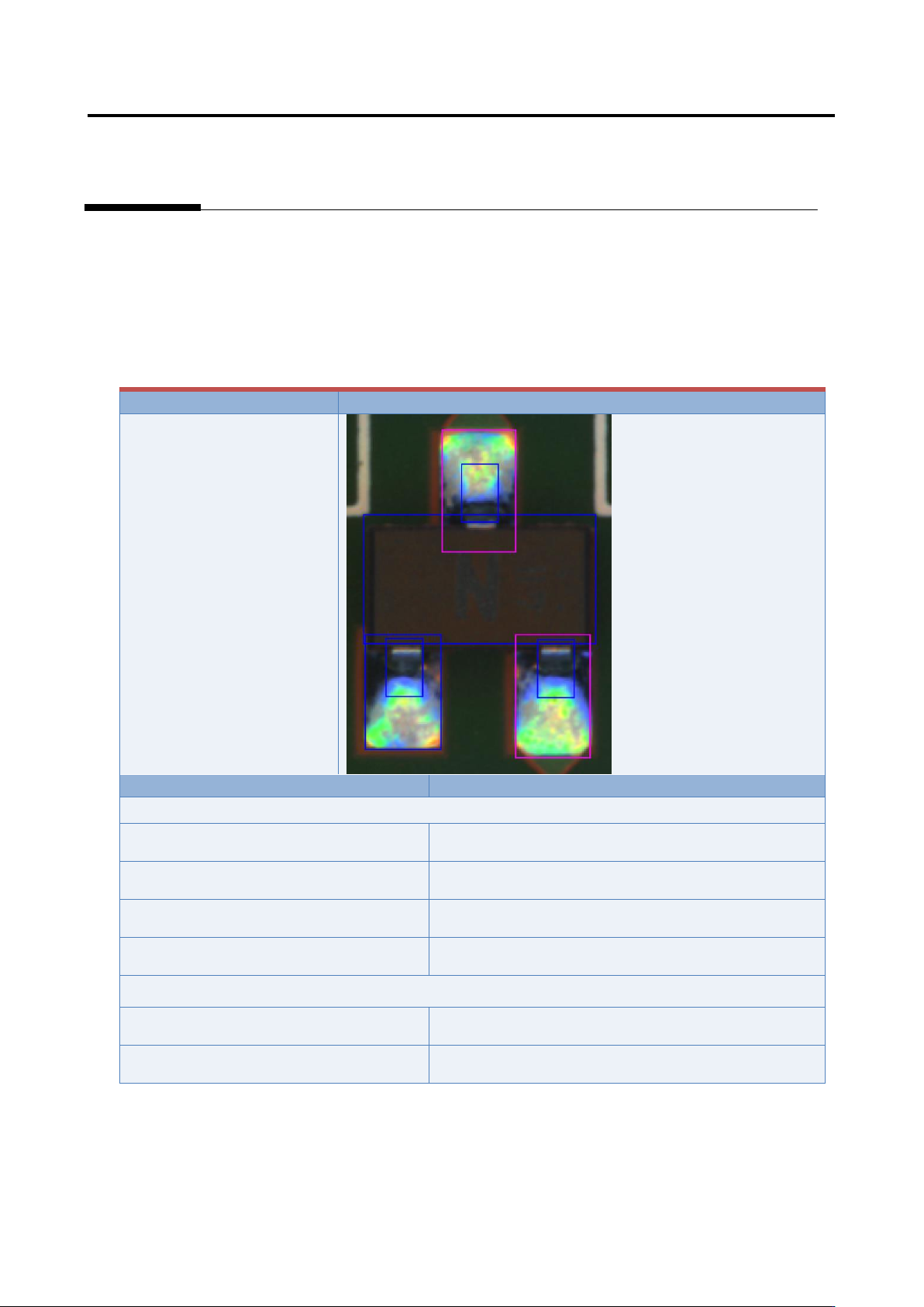
Side connection width short
Cause
Confirmation/repair method
When position does not match between the actual land (electrode) and extracted land (electrode):
The component extraction is not
positioned appropriately.
Refer to Appendix 7.5.
The electrode tip extraction is not
positioned appropriately.
Refer to Appendix 7.7.
The electrode side extraction is not
positioned appropriately.
Refer to Appendix 7.6.
The electrode window size is not
appropriate.
Refer to Appendix 7.5.
The electrode height is not set
appropriately.
Refer to Appendix 8.3.
The inspection criteria are not set
appropriately.
Refer to Appendix 10.1.
Appendix 9. Land Inspection Adjustment Procedure
a-51
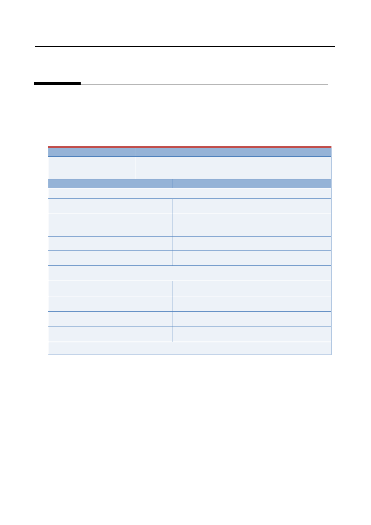
Inspection item 7. Land exposure
Based on the land color detected in the land window, inspect if land is being exposed.
If false call or overlooking still remains in the inspection result, “Land exposure” is displayed.
The inspection result image, cause, and repair method of land exposure are as follows:
Inspection result
Component image (PCB test)
Land exposure
Cause
Confirmation/repair method
When position does not match between the actual land and extracted land:
The land window is not positioned
appropriately.
Refer to Appendix 7.2.
The land window of the peripheral
components of the applicable component
is not positioned appropriately.
Refer to Appendix 7.2.
The fiducial correction is not appropriate.
Refer to Appendix 7.1.
The position correction color is not
appropriate.
Refer to Appendix 7.2.
When position does not match between the actual component (electrode) and extracted component
(electrode):
The component is not extracted in an
appropriate position.
Refer to Appendix 7.5.
The electrode tip is not extracted in an
appropriate position.
Refer to Appendix 7.7.
The electrode side is not extracted in an
appropriate position.
Refer to Appendix 7.6.
The electrode window is not sized
appropriately.
Refer to Appendix 7.5.