Omron V-TS Teaching Manual.pdf.pdf - 第335页
Appendix 9. Land Insp ection Adjustm ent Procedure a- 58 2. Set the inspection area where the ch aracteristic of the NG pro d uct appears . OK product exam ple NG product exam ple Inspection area settin g exam ple 3. Add…
Appendix 9. Land Inspection Adjustment Procedure
a-57
4. Add characteristic quantity of the area other than the inspection area using the pen tool .
Exclude the characteristic quantity of the inspection area using the eraser tool .
5. Change the judgment criteria of land error so that false call is minimized.
This section hereafter describes the adjustment procedure to eliminate overlooking.
Operation procedure
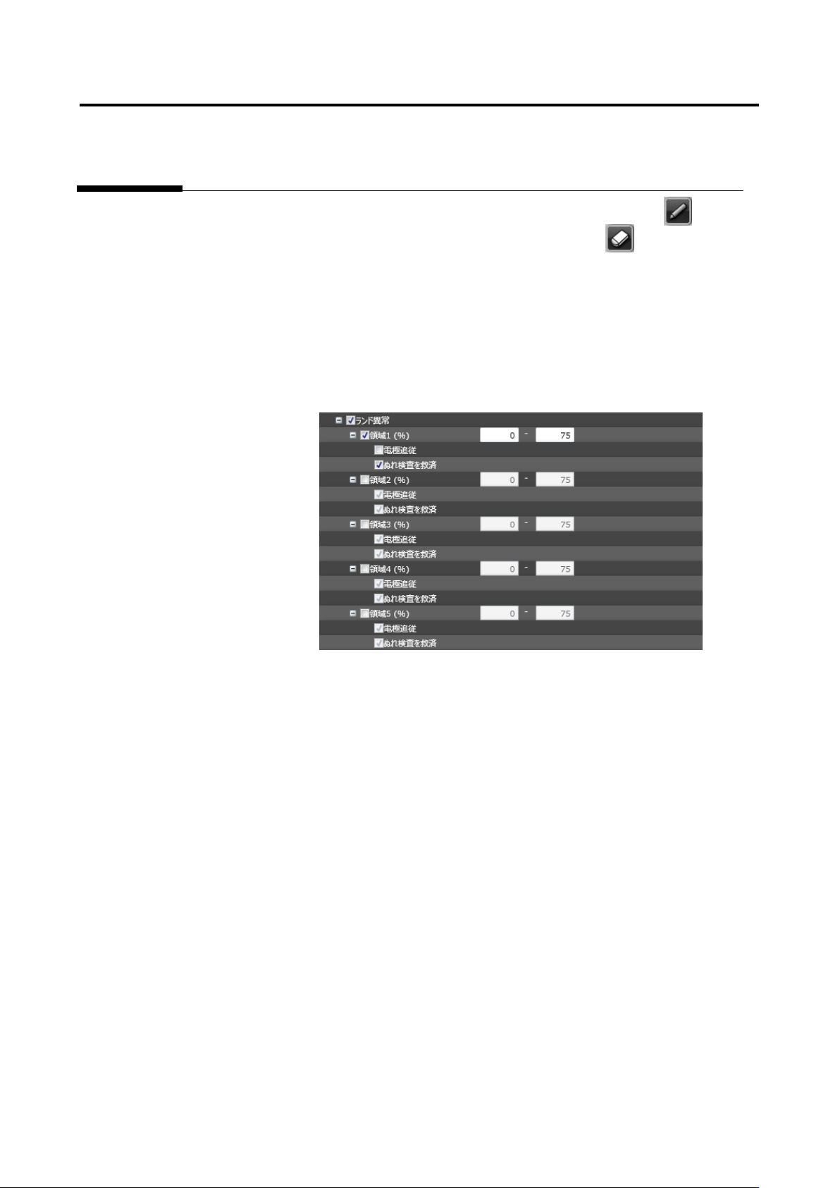
1. Check the land error inspection checkbox.
Appendix 9. Land Inspection Adjustment Procedure
a-58
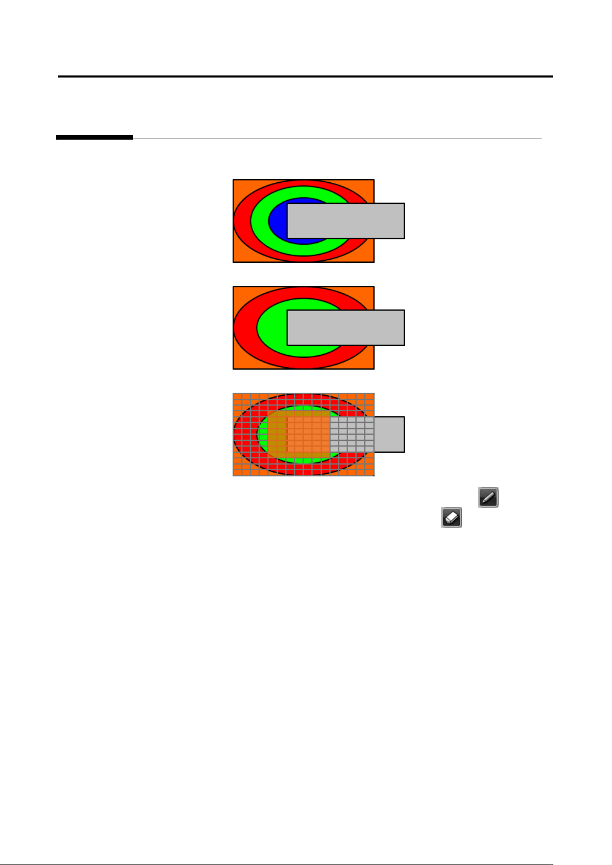
2. Set the inspection area where the characteristic of the NG product appears.
OK product example
NG product example
Inspection area setting example
3. Add characteristic quantity of the inspection area of the NG product using the pen tool .
Exclude the characteristic quantity of the inspection area using the eraser tool .
4. Change the judgment criteria of land error so that overlooking is minimized.
Appendix 9. Land Inspection Adjustment Procedure
a-59
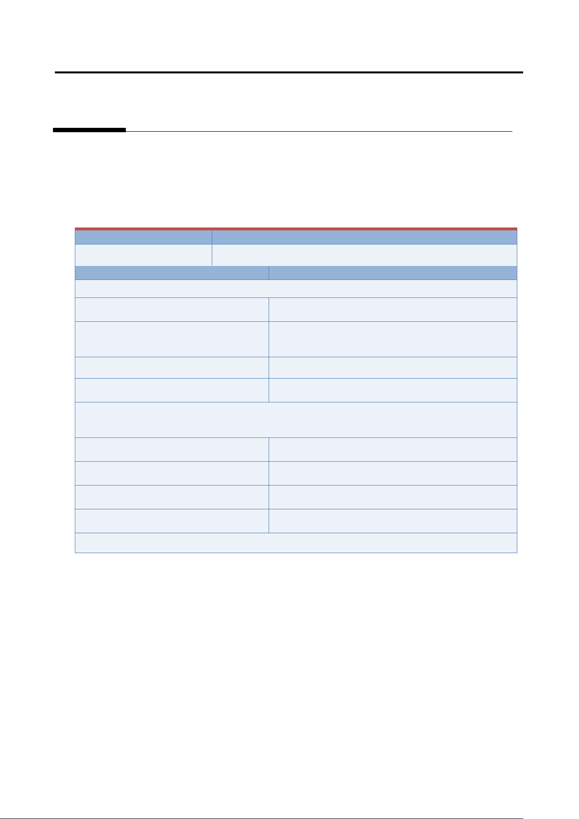
Inspection item 9. Foreign object (land)
Based on the foreign object color detected in the land window, inspect if any foreign objects are in the
land.
If false call or overlooking still remains in the inspection result, “Foreign object (land)” is displayed.
The inspection result image, cause, and repair method of foreign object (land) are as follows:
Inspection result
Component image (PCB test)
Foreign object (land)
(*Image to be pasted)
Cause
Confirmation/repair method
When position does not match between the actual land and extracted land:
The land window is not positioned
appropriately.
Refer to Appendix 7.2.
The land window of the peripheral
components of the applicable component
is not positioned appropriately.
Refer to Appendix 7.2.
The fiducial correction is not appropriate.
Refer to Appendix 7.1.
The position correction color is not
appropriate.
Refer to Appendix 7.2.
When position does not match between the actual component (electrode) and extracted component
(electrode):
The component is not extracted in an
appropriate position.
Refer to Appendix 7.5.
The electrode tip is not extracted in an
appropriate position.
Refer to Appendix 7.7.
The electrode side is not extracted in an
appropriate position.
Refer to Appendix 7.6.
The electrode window is not sized
appropriately.
Refer to Appendix 7.5.