Omron V-TS Teaching Manual.pdf.pdf - 第42页
2.1 Bas ics of Teaching 2- 15 Specify Yes or N o for individual adjustm ent, and click [Adjust]. - Individual Adjustm ent . . . Specify if you want to adjust Land W indow individua lly or not. - ON Land W indow is adjust…
Chapter 2 Inspection Programming
2-14
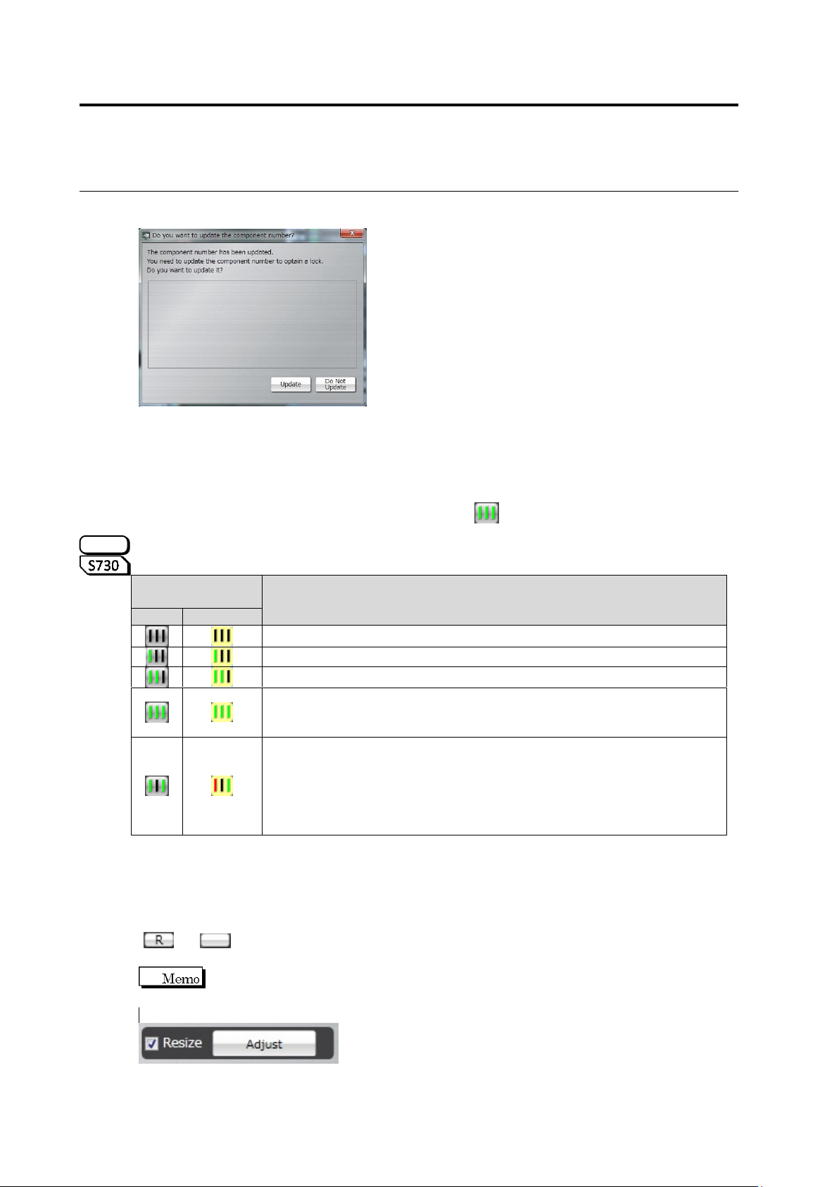
When you select [Do Not Update], the corresponding component number cannot be edited.
If an application program is shut down forcibly, it might occur that the lock state is not released
correctly and component numbers cannot be edited. In this case, select [Tool] – [Forced Lock
Release] on the menu bar, and select a lock release target to release the lock.
<Progress Signal>
The lighting status of the three signal bars shown in row in the Component Number List
represents the teaching status of individual product numbers.
The component numbers for oblique inspection are displayed in a different background color.
The left signal bar lights up in red if the oblique image is not captured yet.
Oblique
Inspection
Product Number Teaching Progress
No
Yes
The component number information is not specified yet
A sample component for the component number has been registered
All component windows have been automatically adjusted
All component windows have been automatically adjusted, the model
has been registered, and component and electrode heights have been
configured
The model has been registered, but the windows are not automatically
adjusted yet
(The number of electrodes of the component number has changed, or
the number of electrodes of the component number does not match the
number of lands because the process to add or delete a land is on the
way.
<Auto Adjustment>
Use the [Adjust] button at the bottom of the Component Number List to automatically adjust
the windows.
The [Automatic Adjustment] button is enabled only when the component number lock is locked
( -> ).
The [Adjust] button is available on the Component Registration screen and Criteria
Setting (Product No.) screen.
S720A
2.1 Basics of Teaching
2-15
Specify Yes or No for individual adjustment, and click [Adjust].
- Individual Adjustment . . . Specify if you want to adjust Land Window individually or not.
- ON Land Window is adjusted individually based on the bare board image.
- OFF Deployment is done for Land Window with the same size and relative
position as the representative component.
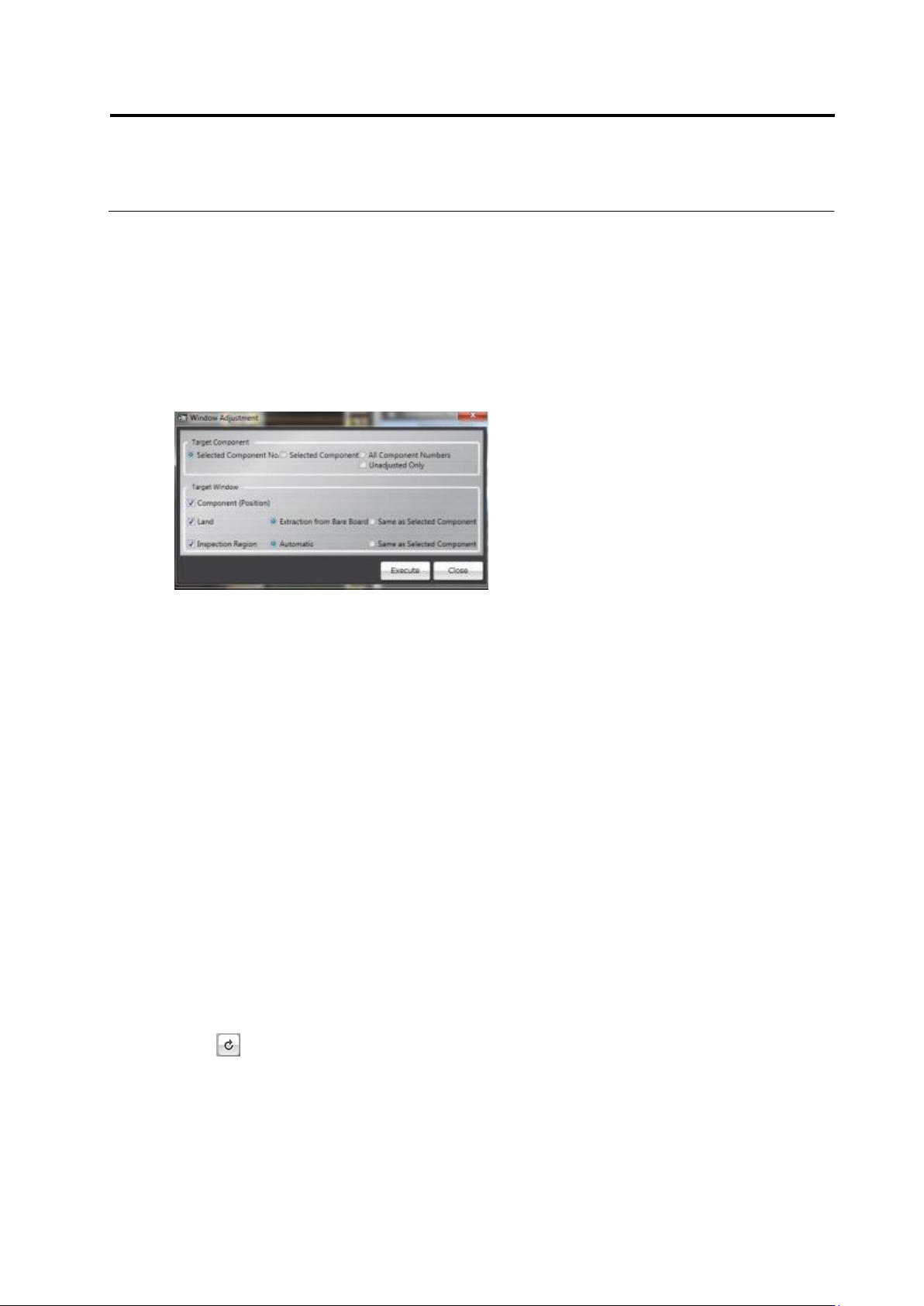
Clicking [Adjust] displays the window adjustment dialog box.
Specify a target component and window, and click [Execute].
- Target Component . . . Selects a target component.
- Selected Component No. Selected component number is set as a target.
- Selected Component Selected component is set as a target.
- All Component Number All component numbers are set as target.
- Unadjusted Only . . . Unadjusted component numbers or components are set as target out of
the component numbers or components selected in the Target
Component area.
- Target Window . . . Selects a target window.
- Component (Position) Moves the component window to the inspection criteria position.
- Land Adjusts the Land Window.
- Extract from Bare Board Extracts a land from the bare board image and adjusts
the Land Window.
- Same as Selected Component Sets the Land Window of the target component same as
that of the selected component.
- Inspection Region Adjusts the inspection range window.
- Automatic Adjusts the inspection range window automatically.
- Same as Selected Component Sets the inspection range window of the target
component same as that of the selected
component.
< Update >
Click on top-right component number list to update the list.
Chapter 2 Inspection Programming
2-16
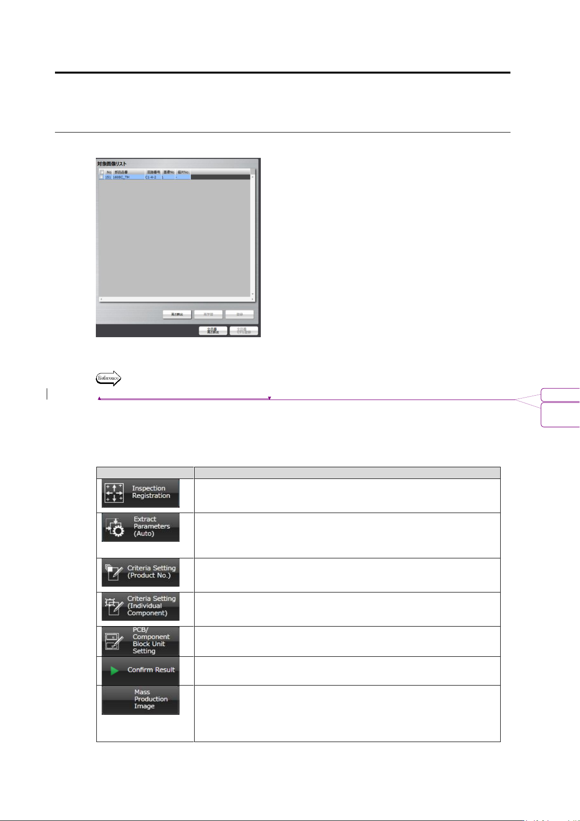
■ Target Image List
For the component of the thumbnail image displayed in the image display area, height
calculation, re-learning, and so on are performed.
For the details of the method to operate the image on the target image list, refer to 2.5
“Registering the Component Number Model.”
(6) Display Switch Tabs
Display switch tabs are provided. They are positioned in the order of the depth of teaching
progress (from left to right).
The following shows the operation available with each tab.
Tab
Outline of Operation
Load the mounting data and register the components to inspect.
Specify the inspection windows (component body, land and
electrode windows) by the unit of component number.
Select a component thumbnail for the component number, based on
which a model is calculated. The characteristic parameters for the
component number is then automatically extracted, and the model is
registered in the library.
Set the criteria values for each of the inspection items for the
component number.
Edit a component number model image registered in the library.
Specify the criteria values for each of inspection items for individual
components.
Perform Component Block Unit settings (position change, copy or
deletion) and mark settings (2D code).
Inspection images and adjustment images are read in, the PCB is
tested, and the result is listed.
Load mass-production images specified by Q-upNavi and images
judged as inspection NG by v-TS, select an image to register it in
the library. In addition, images checked on the [Save Image] column
are also included in the mass-production images regardless of the
inspection result.
書式変更: フォント : 10 pt
削除: Registering the Component Number
Model