Omron V-TS Teaching Manual.pdf.pdf - 第136页
2.9 Setti ng Oblique Inspection 2- 109 2.9 Setting Oblique Inspection Oblique inspection requ ires the settings f or oblique inspection targ et component n umbers , oblique image capturin g, inspection criteri a and dire…
Chapter 2 Inspection Programming
2-108
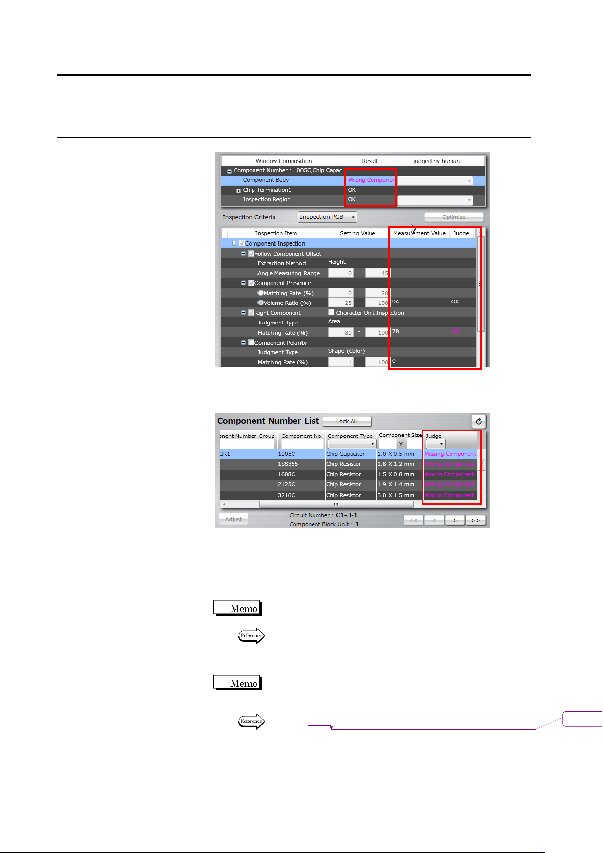
The Inspection Criteria Setting screen for a component number
displays the result ("OK" or Fault Name) in the Judge column in the
Component Number List.
3.
Adjust the position and size of the windows where an inspection
fault is output as required.
4.
Select the inspection item to modify, and change the inspection
criteria or edit the model.
The changed criteria values replace the old values in the library
when the inspection program is saved in the library.
Refer to "2.6.1 Criteria Setting (Product No.)" for criteria value
editing by the unit of component number, and "2.6.2 Criteria
Setting (Individual Component)" for the same by the unit of
individual component.
If the detected position does not match the image, editing of the
component top color or electrode color (model editing
operation) is required prior to changing the criteria value.
Refer to P2-135 "2.15.3 Editing a Model" for the model editing
procedure.
削除
: 2-132
2.9 Setting Oblique Inspection
2-109
2.9 Setting Oblique Inspection
Oblique inspection requires the settings for oblique inspection target component numbers,
oblique image capturing, inspection criteria and direction. This chapter describes the procedures
to make individual settings and test PCBs for oblique inspection.
You cannot specify oblique inspection for BGA/CSP, other bottom electrode
component, and insertion component.
2.9.1 Setting Oblique Inspection Target Component Number
This section explains the procedure to specify an existing component number to the target of
oblique inspection.
Refer to "2.4.5.1 Component Setting" for the procedure to specify a new component number to the
target.
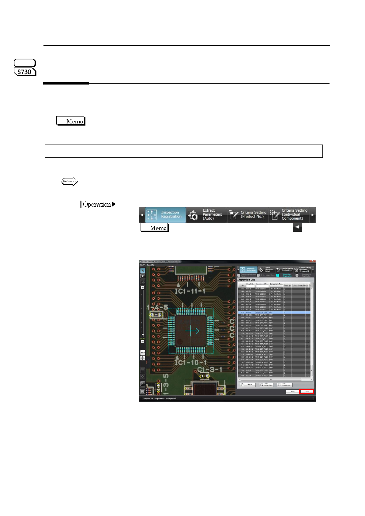
1.
Select the [Inspection Registration] tab.
If the [Inspection Registration] tab is hidden, click at the
left to display it.
2.
The display moves to the Inspection Registration screen. Click
[Next].
S720A
Chapter 2 Inspection Programming
2-110
3.
The Component Registration screen is displayed. Select the
component number for oblique inspection in the Component
Number List, and select "Yes" in the oblique inspection row in the
PCB Information panel.
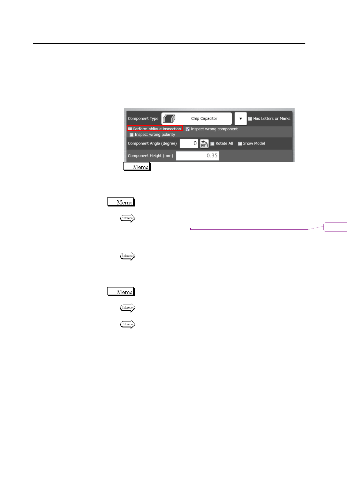
The component cannot be set to "Yes", if the component type is
"BGA/CSP" or "Others (Bottom Electrode)".
4.
If the PCB test has not been conducted for the inspection program,
conduct the PCB test.
Unless the PCB test has been conducted, it is not allowed to capture
oblique images.
For the procedure to conduct the PCB test, refer to Section
エラー
!
参
照元が見つかりません。
“Testing Using PCBs.”
5.
Save the inspection program.
Refer to "2.11.1 Saving an Inspection Program" for the procedure to
save the inspection program.
6.
Exit inspection program editing and capture oblique image with the
inspection system.
If the inspection program is in the process of editing with v-TS, the
program cannot be opened on the system to capture oblique image.
Refer to "2.14 Quitting Program Editing" for the procedure to exit
inspection program editing.
Refer to the Operation Manual of inspection machine: P3-10 "3.2.4
Capturing Oblique Image" for the procedure to capture oblique image.
削除
: 2.8.1