Omron V-TS Teaching Manual.pdf.pdf - 第203页
Chapter 2 Insp ection Progr amming 2- 176 Use the com bo box to switc h between X and Y axes of the scatter chart. Selecting/unse lecting the check box switches betwee n targets to show/hide in th e s catter chart. (6) T…
2.15 Modifying an Inspection Program
2-175
Judgement results (OK/NG) are only displayed after PCB
testing.
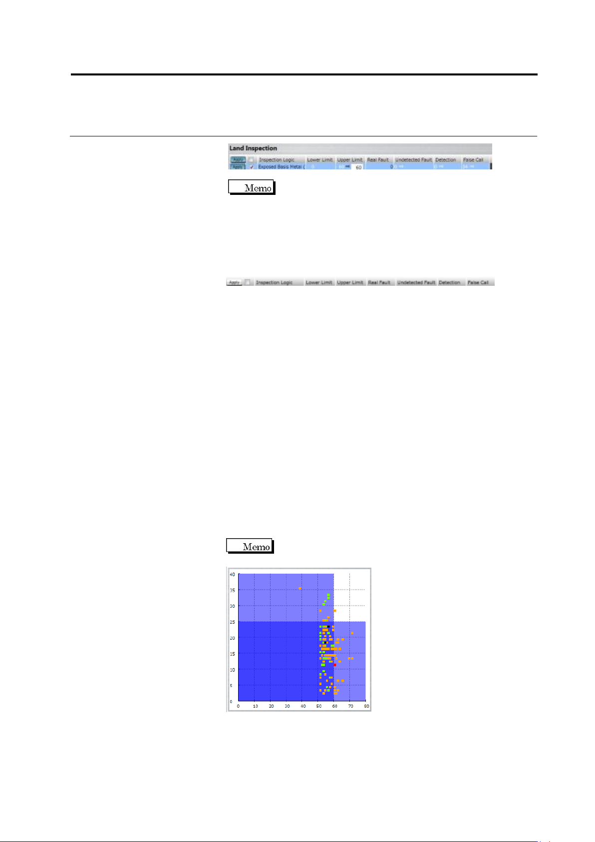
(1) Displays component number group and component number
name.
(2) Displays the setting list of component inspection, electrode
inspection, land inspection, and wettability error inspection.
Apply to: If the [Apply] toggle button is ON, clicking the [Apply]
button reflects the change.
Checkbox: Specify ON/OFF of inspection item.
Inspection Logic: Displays inspection item name.
Lower Limit/Upper Limit: Specify inspection setting values.
Real Fault: Displays the number of real faults registered in this
inspection item.
Undetected Fault: Displays the number of the real faults which were
registered with this inspection item and undetected.
Detection: Displays the number of the real faults which were
registered with this inspection item and detected.
False call: Displays the number of the OK products which were
registered with this inspection item and detected as faults by
mistake.
(3) By clicking the toggle button of the electrode group name,
electrode groups are switched with each other.
(4) Displays the wettability inspection result.
(5) Displays a histogram.
A scattered chart is displayed if a Boolean expression is
selected.
Chapter 2 Inspection Programming
2-176
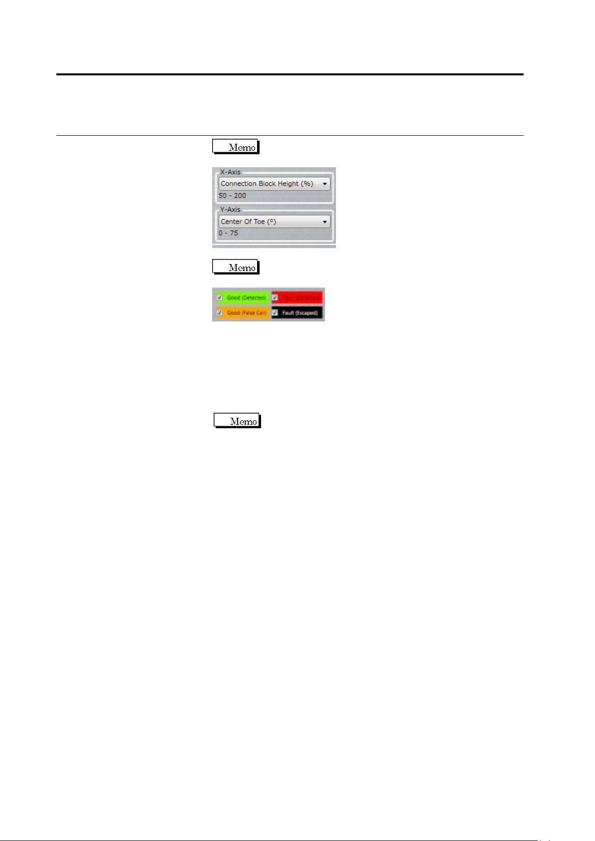
Use the combo box to switch between X and Y axes of
the scatter chart.
Selecting/unselecting the check box switches between
targets to show/hide in the scatter chart.
(6) The statistic information of the inspection result is displayed on a
per component basis.
5.
By clicking [Apply], the criteria of the inspection items with which
the [Apply] toggle button is enabled are updated.
If the inspection criteria have been changed manually, the
numerical values are updated by clicking the [Update Result]
button.
6.
Click [Close] to exit the inspection criteria setting screen.
2.15 Modifying an Inspection Program
2-177
2.15.5 Registering Visual Check Results
Visual check results can be registered for each window of model images.
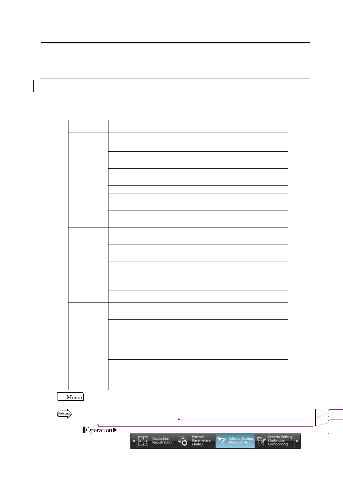
Visual check items that can be registered
Window
Item
S500
/S720
S720A
S730
Component
Body Window
Component Presence
Yes
Yes
Yes
Right Component
Yes
Yes
Yes
Component Polarity
Yes
Yes
Yes
Flipped Component
Yes
Yes
Yes
Offset X
Yes
Yes
Yes
Offset Y
Yes
Yes
Yes
Component Skew
Yes
Yes
Yes
Component Height
Yes
Component Tilt (0-180 deg.)
Yes
Component Tilt (90-270 deg.)
Yes
Parallel Lifted Component
Yes
Electrode
Window
Wetting Error
Yes
Yes
Yes
Side Overhang
Yes
Yes
Yes
End Overhang
Yes
Yes
Yes
End Overlap
Yes
Yes
Yes
No Electrode
Yes
Yes
Yes
Electrode Posture (Color
Dispersion)
Yes
Yes
Yes
Electrode Posture (Side Bend)
Yes
Yes
Yes
Electrode Posture (Color
Dispersion (Oblique))
Yes
Yes
Land Window
Wetting Error
Yes
Yes
Yes
Exposed Basis Metal
Yes
Yes
Yes
Abnormal Land
Yes
Yes
Yes
Foreign Material on Land
Yes
Yes
Yes
Exposed Basis Metal (Oblique)
Yes
Yes
Abnormal Land (Oblique)
Yes
Yes
Inspection
Range
Window
Solder Ball
Yes
Yes
Yes
Solder Bridge
Yes
Yes
Yes
Foreign Object (Component
Peripheral)
Yes
Yes
Yes
Solder Ball (Oblique)
Yes
Yes
Solder Bridge (Oblique)
Yes
Yes
Wetting Error shows the result of Boolean expressions set in the [Detailed Settings].
For the setting procedure, refer to "2.15.4 Optimizing Boolean Expressions and Inspection
Criterion Values."
1.
Select the [Criteria Setting (Component Number)] tab.
書式変更: フォント : Arial, 10 pt
削除: Optimizing Boolean Expressions
and Inspection Criterion Values