Omron V-TS Teaching Manual.pdf.pdf - 第129页
Chapter 2 Insp ection Progr amming 2- 102 By clicking [Exec ute], an inspection criterion va lue is selected from the distribution of the m easured values of the selected target inspection so that th e number of undetect…
2.8 PCB Testing/Result Check
2-101
3.
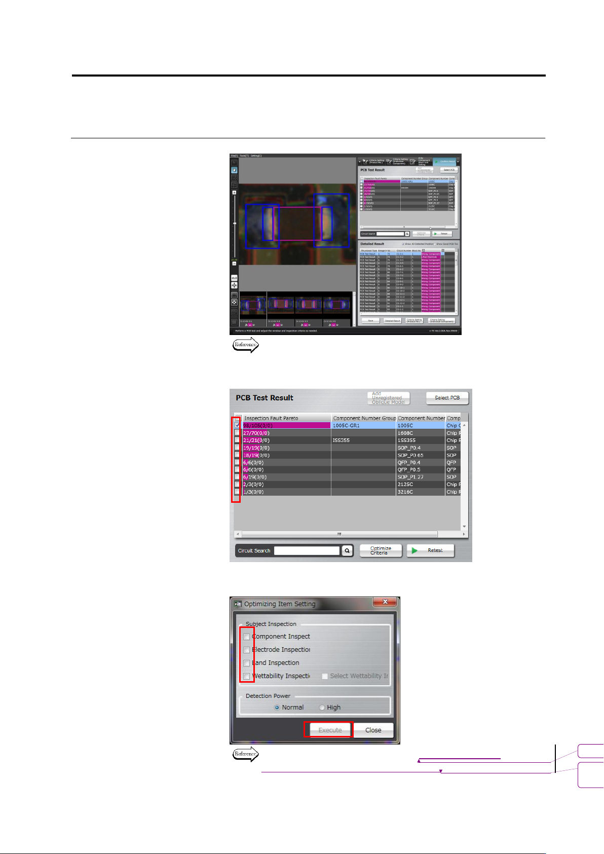
Check the test result.
Refer to the next page for how to interpret the test result.
4.
Select the component number check box and click [Optimize
Criteria].
The criteria optimization screen appears. Configure inspection items
and outputs to optimize, and click [Execute].
For details of optimization, see 2.15.4 “Optimizing Boolean
Expressions and Inspection Criterion Values.”
書式変更: フォント : 9 pt
削除
: Optimizing Boolean Expressions
and Inspection Criterion Values
Chapter 2 Inspection Programming
2-102
By clicking [Execute], an inspection criterion value is selected from
the distribution of the measured values of the selected target
inspection so that the number of undetected faults and false call
faults becomes minimal.
The inspection criteria can also be optimized by the method of
Step 4 of Section 2.8.1 “Testing Using PCBs.” However, there
are two differences as follows:
- On the inspection criteria setup screen of Section 2.15.4 “Optimizing
Boolean Expressions and Inspection Criterion Values,” inspection criterion
value must be set up by selecting a component number one by one. On the
other hand, when using the method of Step 4 of Section 2.8.1 “Testing
Using PCBs,” inspection criterion values for all component block numbers
whose checkbox is ON can be set up in block.
- When criteria are optimized, the optimization results of all the checked
component numbers are applied forcedly. So, save the inspection program
before executing optimization. To cancel application, open the inspection
program saved before optimizing the criterion.
5.
Click [Retest] to perform PCB test.
Up to 3 PCBs can be selected.
書式変更: フォント : Arial, 9 pt
削除: Optimizing Boolean Expressions and
Inspection Criterion Values
書式変更: フォント : Arial, 9 pt
削除: Testing Using PCBs
2.8 PCB Testing/Result Check
2-103
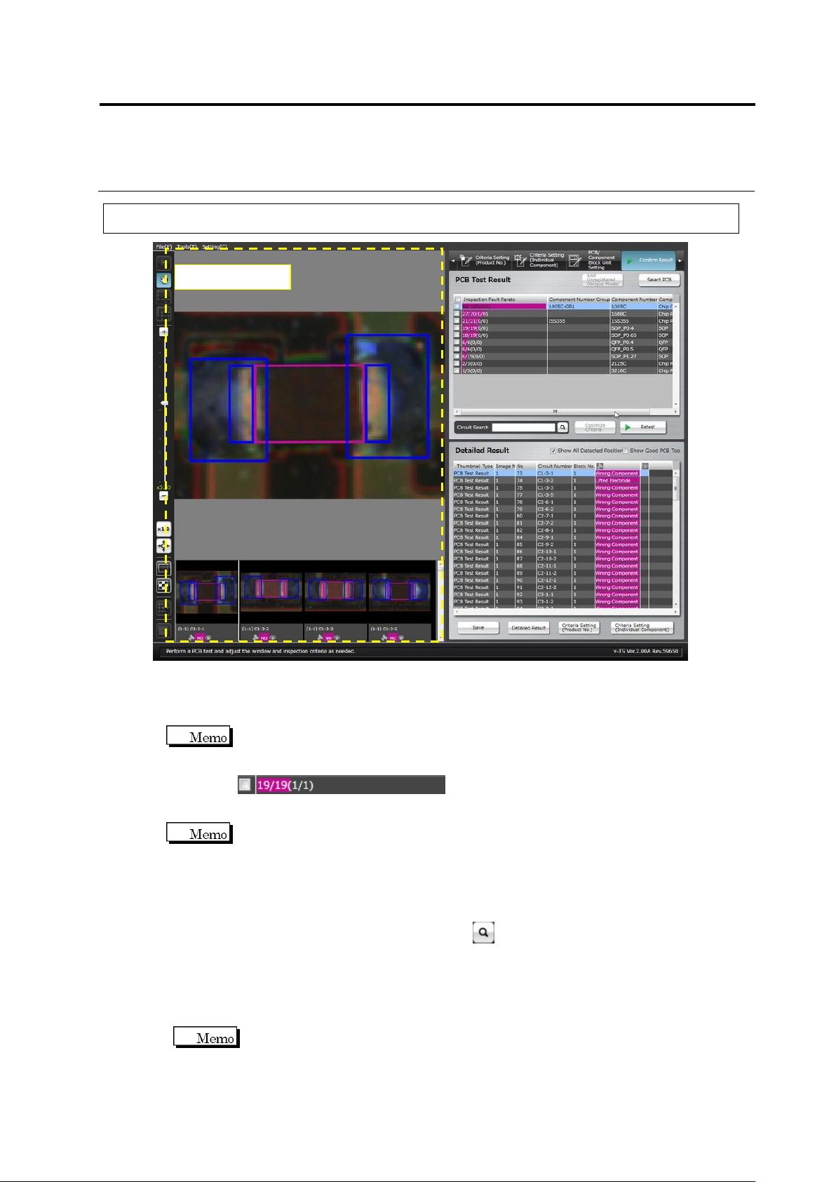
2.8.2 Interpreting PCB Test Result
・ PCB Test Result
Shows the PCB test result as the number of inspection faults in a Pareto chart by the unit of
component number.
The numbers displayed on the inspection fault palate indicate the resultant numbers of
component inspection.
NG components / All components (detected faults / actual faults)
Detected faults: The number of faults which were detected as faulty by the inspection
Actual faults: The number of visually registered actual faults
Reducing undetected fault means reducing the difference between the detected faults and
actual faults.
・ Detailed Result
Displays a list of the inspection fault components and judgment results pertaining to the
component number selected in the PCB Test Result list.
Enter a circuit name in [Circuit Search] and click button, then select a line with the same
name from the detailed result list.
Click the [Show Good PCB Too] checkbox ON also to display components judged good.
Selecting the [Show All Detected Position] checkbox displays the Component Body Window,
electrode windows and land windows extracted in inspection. Deselecting the checkbox
does not display the windows.
If multiple inspection items are judged faulty for a single component, the result is
displayed in the order from smaller fault codes.
Component Image