Omron V-TS Teaching Manual.pdf.pdf - 第212页
2.15 M odifying an Inspection Pr ogram 2- 185 7. Only the eff ective components out of the destinati on com ponents whose radio button on t he window displa y colum n is ON are displayed. 8. Press the [Close ] button to …
Chapter 2 Inspection Programming
2-184
2.15.8 Setting up Destination
It is able to set up destination on the inspection program being edited.
Execution result can be confirmed for each destination setting.
Refer to Section 2.8.1 “Testing Using PCBs”.
1.
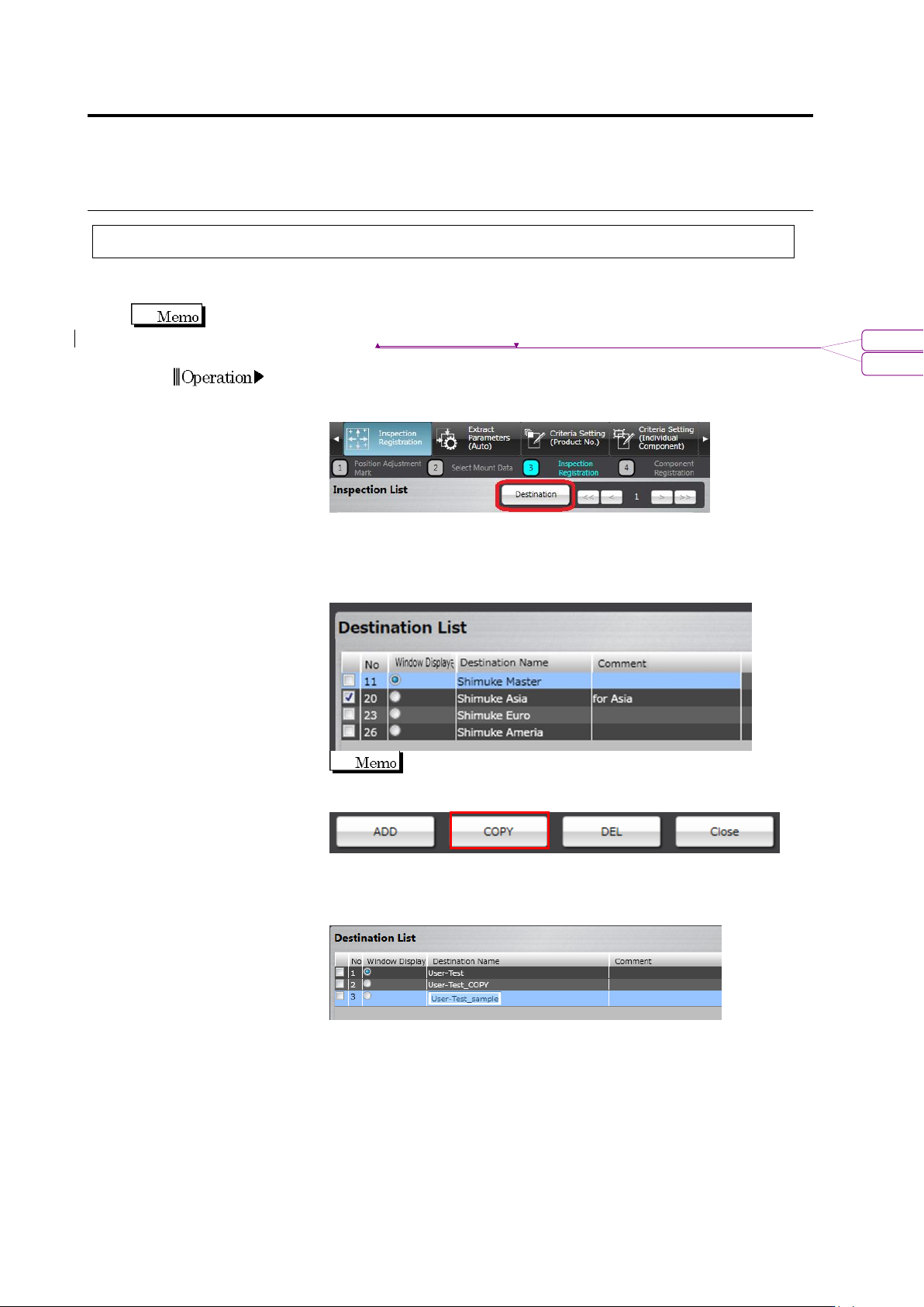
On the [Register Inspection] tab, click the [Next] button.
2.
Press the [Destination] button.
3.
By clicking the [Add] button, the destination can be added. In
addition, by checking the checkbox of a destination on the
destination list screen and clicking [Copy], the selected destination
is copied.
The numbers on the destination list correspond to the
numbers of headers of destinations on the inspection list.
4.
By double-clicking a destination name on the [Destination Name]
column, the name can be changed or set up. In addition, by
double-clicking the [Comment] column, a comment can be entered.
5.
Register destination for the necessary number by performing steps
3 and 4 above repeatedly.
6.
Unnecessary destinations can be deleted by checking their
checkboxes and clicking [Delete].
書式変更: フォント : Arial
削除: Testing Using PCBs
2.15 Modifying an Inspection Program
2-185
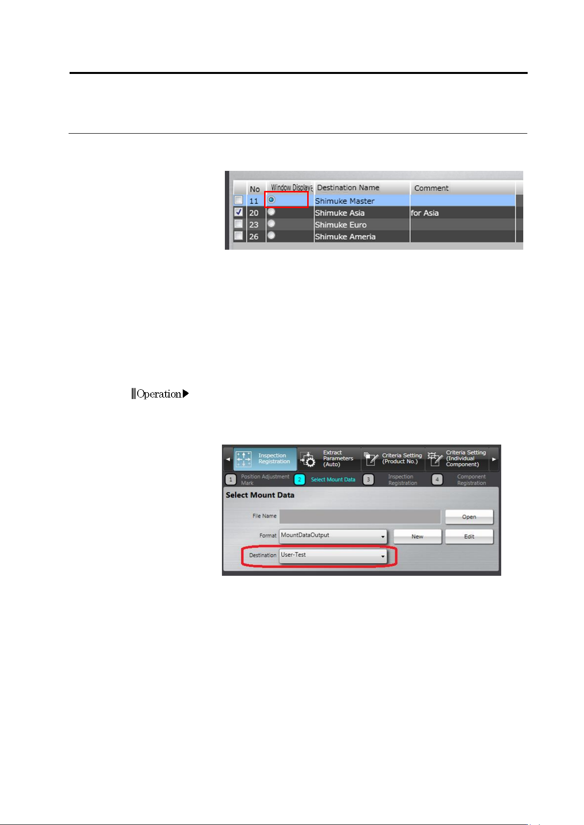
7.
Only the effective components out of the destination components
whose radio button on the window display column is ON are
displayed.
8.
Press the [Close] button to return to the [Register Inspection]
screen.
According to the mount data you have, set up destination on each component number or circuit
by one of the following two methods.
Method 1: When there is mount data covering the circuits and component numbers for all
destinations:
By this procedure, a master destination data including all circuits and component numbers is
created. Then, each component number and circuit included in each destination is set up.
1.
Press the [Return] button to return to the [Select Mount Data]
screen.
2.
Click the [Destination] pull-down menu to select a master
destination.
3.
Read in the mount data to position it.
Chapter 2 Inspection Programming
2-186
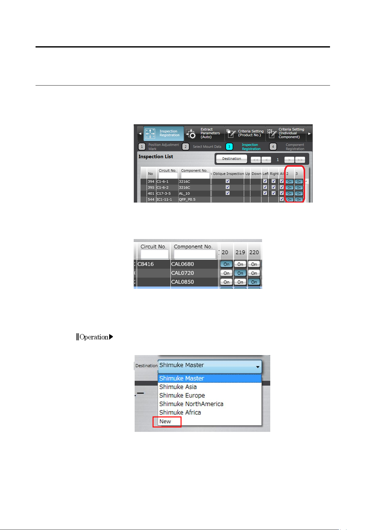
4.
When the [Next] button is clicked, software operates as follows:
If the component is included in the mount data, the [ON] button is
set ON for the component number included in each destination on
the list. If the component is not included in the mount data, the [ON]
button is set OFF.
5.
To add component numbers to a circuit manually as a destination,
select the target circuit, and click [Add Component Number]. For the
component numbers with the same circuit number, the circuit
number is displayed for the first component number only.
Method 2: When there is mount data for each destination:
By this procedure, mount data corresponding to each destination is read in. Then, circuits and
component numbers are set up.
1.
Press the [Return] button to return to the [Select Mount Data]
screen.
2.
Click the [Destination] pull-down menu to select [New].
3.
Read in the mount data to position it.
4.
Execute steps 2 and 3 repeatedly for the number of necessary
destinations.