Omron V-TS Teaching Manual.pdf.pdf - 第176页
2.15 M odifying an Inspection Pr ogram 2- 149 <Color Ta ble Editing Tools> The color table ed iting tools are displa yed when editing c haracteristic param eters other than characters or s ymbols. Use the tools to …
Chapter 2 Inspection Programming
2-148
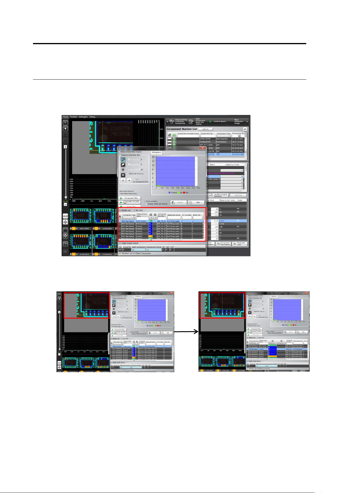
(15) Per-pin-No. basis
By checking the Per-pin-No. basis item on the model editing screen, inspection result can be
displayed not only on a per component No. basis but also on a per pin No. basis.
Model editing screen with the Per-pin-No. basis item checked
In addition, selecting a pin moves the screen so as to display the selected pin in the screen
center.
Case: Switching pin numbers from 1 to 3
2.15 Modifying an Inspection Program
2-149
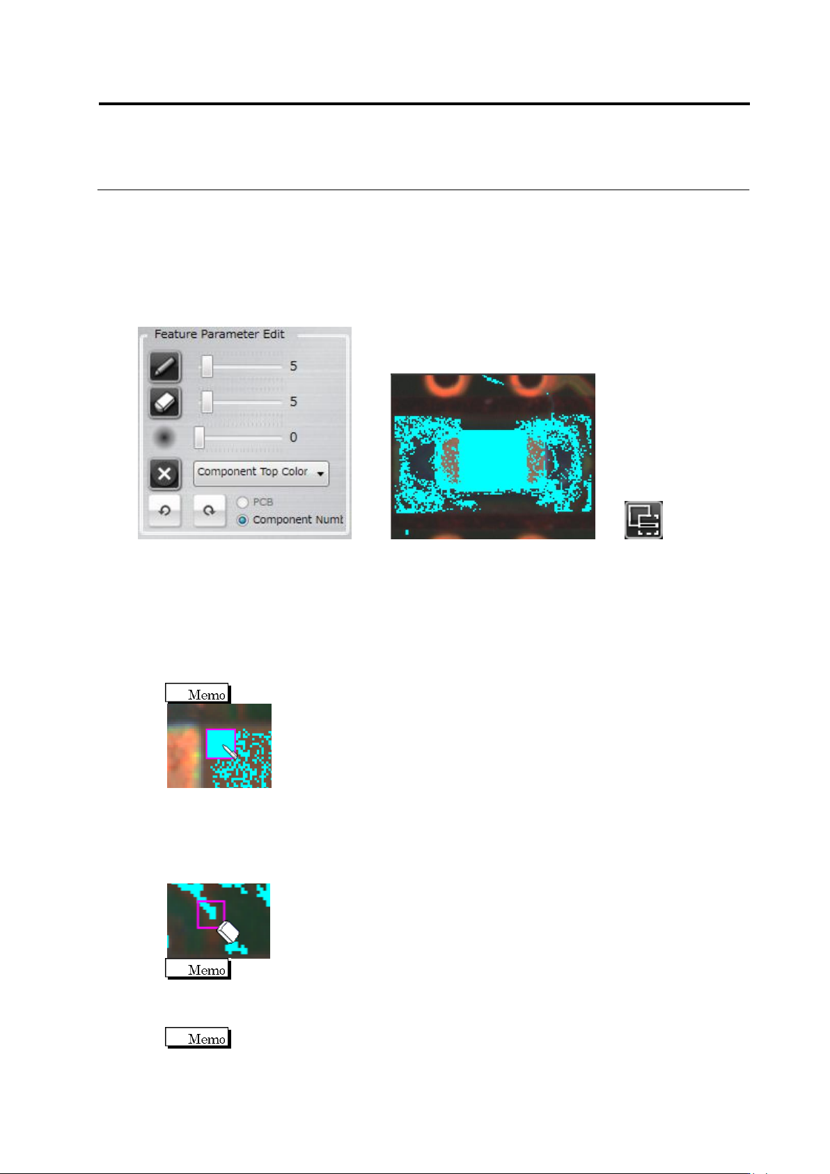
<Color Table Editing Tools>
The color table editing tools are displayed when editing characteristic parameters other than
characters or symbols.
Use the tools to add or delete colors to/from the color table after checking the extracted colors in
the component thumbnail image.
Editing Tools Component Thumbnail Image (Image in the Inspection Region Window)
(1) Displaying Characteristic Parameters
Selecting/unselecting the check box switches between presence and absence of binarized
display on the image.
(2) Pen Tool
Click the button to enable the pen tool.
Click the pixel to extract in the component thumbnail image. The color of the clicked pixel is
added to the color table. The pen size can be adjusted with the slide bar.
The pen size can be specified in the range of 1 to 41 pixels.
(3) Eraser Tool
Click the button to enable the eraser tool.
Click the extracted pixel (shown in aqua color) to erase in the component thumbnail. The
color of the clicked pixel is removed from the color table. The eraser size can be adjusted
with the slide bar.
The eraser size can be specified in the range of 1 to 41 pixels.
(4) Expansion Range Setting
Specify the expansion size of the pixel selected by the pen or eraser tool, using the slide bar.
The expansion size can be specified in the range of 0 to 20.
(1)
(2)
(3)
(4)
(5)
(6)
(8)
(7)
(9)
(10)
Chapter 2 Inspection Programming
2-150
(5) Clear Button
Click the button to delete all the color settings from the color table.
(6) Feature Parameter
Display the feature parameter of the editing target. You can select from multiple feature
parameters in the case of component extraction and missing component.
(7) UNDO Button
Click the button to undo the changes added to the color table. However, changes made prior
to switching the feature parameter or component number menu item cannot be canceled.
(8) REDO Button
Click the button to redo the canceled changes to the color table. However, changes
canceled prior to switching the feature parameter or component number menu item cannot
be redone.
(9) Characteristic Parameter Radio Button
Clicking the radio button allows selection of a PCB or a component number that retains the
characteristic parameters. You cannot select it if selection of a PCB or a component number
is not available for the characteristic parameters.
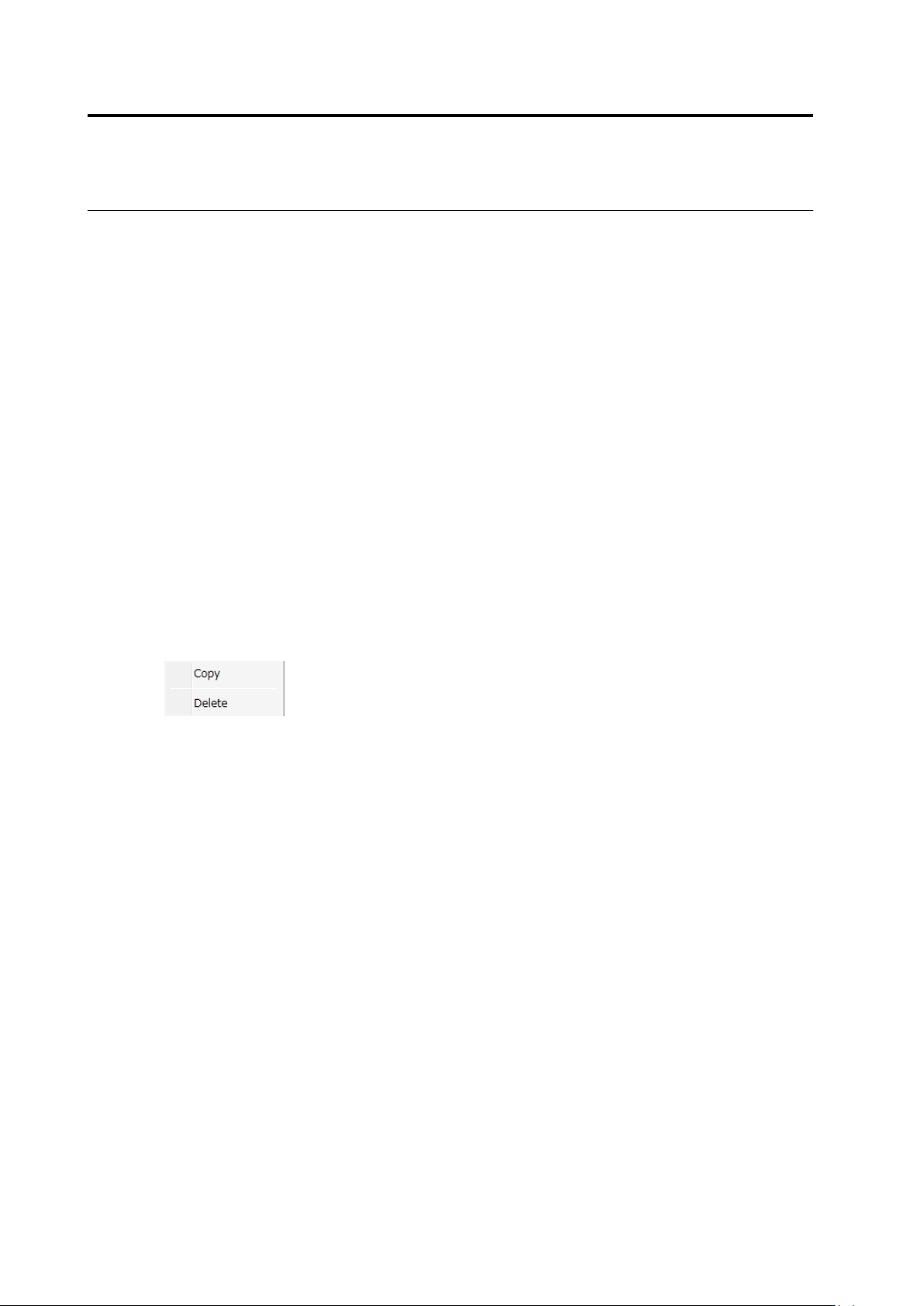
(10) Mask Add Button
Click the button to add a mask. When it is not available, the button cannot be clicked. After
selecting the added mask, it can be copied and deleted.