Omron V-TS Teaching Manual.pdf.pdf - 第142页
2.9 Setti ng Oblique Inspection 2- 115 3. Check the test result. Click [Detailed Resu lt] to check the result of individual oblique inspection items . Refer to "2.8.2 Interpreting PCB Test Result" and the subse…
Chapter 2 Inspection Programming
2-114
2.9.4 Including Oblique Inspection in PCB Test
Perform PCB testing on the PCB used to capture oblique image, to check the validity of the
oblique inspection criteria.
1.
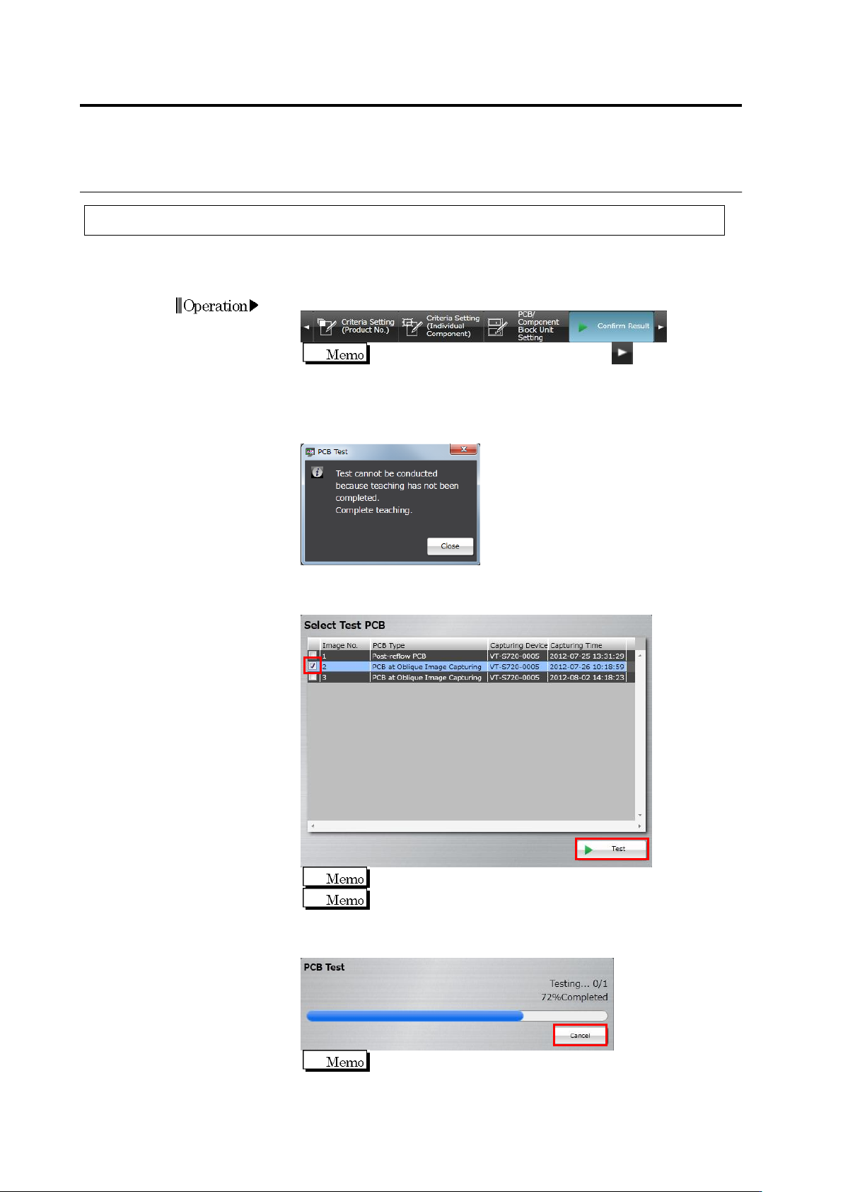
Select the [Confirm Result] tab.
If the [Confirm Result] tab is hidden, click at the right to
display it.
The following dialog appears if direct view inspection teaching is not
complete for some component numbers. Click [Close], and complete
teaching for all component numbers.
2.
Turn ON the checkbox to which the PCB type is "PCB at Oblique
Image Capturing" or “Adjusted Image (Oblique)”, and click [Test].
Up to three PCBs can be selected.
The master PCB is displayed at the top.
The test starts and the progress is shown in the progress bar.
Click [Cancel] to abort testing.
The first test on a PCB used to capture oblique image requires
more time than following tests, due to the necessity of image
capture route calculation.
2.9 Setting Oblique Inspection
2-115
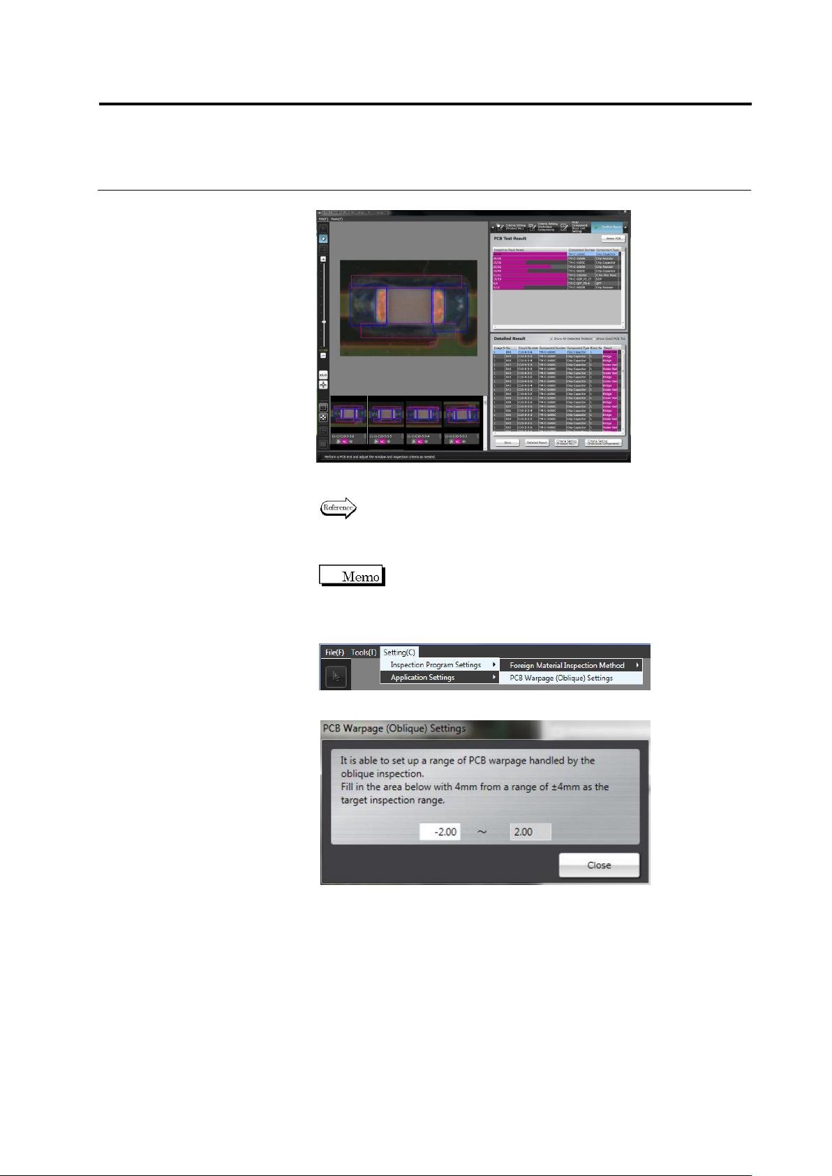
3.
Check the test result.
Click [Detailed Result] to check the result of individual oblique
inspection items.
Refer to "2.8.2 Interpreting PCB Test Result" and the subsequent
pages for the procedure to operate the PCB test result check
screen.
If the inspection range is not appropriate due to warpage of the
PCB, adjust the allowable quantity of warp by the following
steps.
1. On the [Settings] menu, click [Inspection Program Settings] - [PCB
Warpage (Oblique) Settings].
2. The screen below is displayed.
Fill in the lower limit of warpage as a range of -4.00mm to 0.00mm.
3. Click [File] - [Release] to release the inspection program.
Chapter 2 Inspection Programming
2-116
2.10 Setting Secondary Reflection Inspection
This section describes the setup procedure of the secondary reflection inspection.
It is unable to set up the secondary reflection inspection on a component with an
inspection range window of 10mm or more square.
2.10.1 Setting a target component for the secondary reflection inspection
This section describes a procedure to change an existing component to a target component of
the secondary reflection inspection.
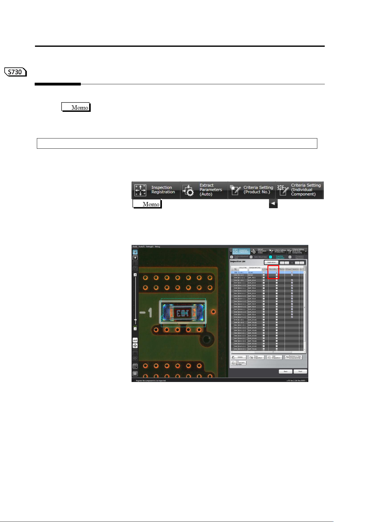
1.
Select the [Register Inspection] tab.
If this tab is not being displayed, click on the left
end. The hidden tab appears.
2.
The screen moves to the inspection registration screen. Select a
target component of the secondary reflection inspection from the
inspection list, and check the [Secondary Reflection] checkbox.
3.
Adjust and save the inspection program, or release it. (On the menu,
select [File] - [Save Adjustment] or [Release].) After it is saved,
close the inspection program.
Operation procedure