Omron V-TS Teaching Manual.pdf.pdf - 第194页
2.15 M odifying an Inspection Pr ogram 2- 167 If a component t ype is electrolytic capacitor, the lifted com ponent window is configured as shown below. T wo component tilts are calculate d in horizontal and vertical dir…
Chapter 2 Inspection Programming
2-166
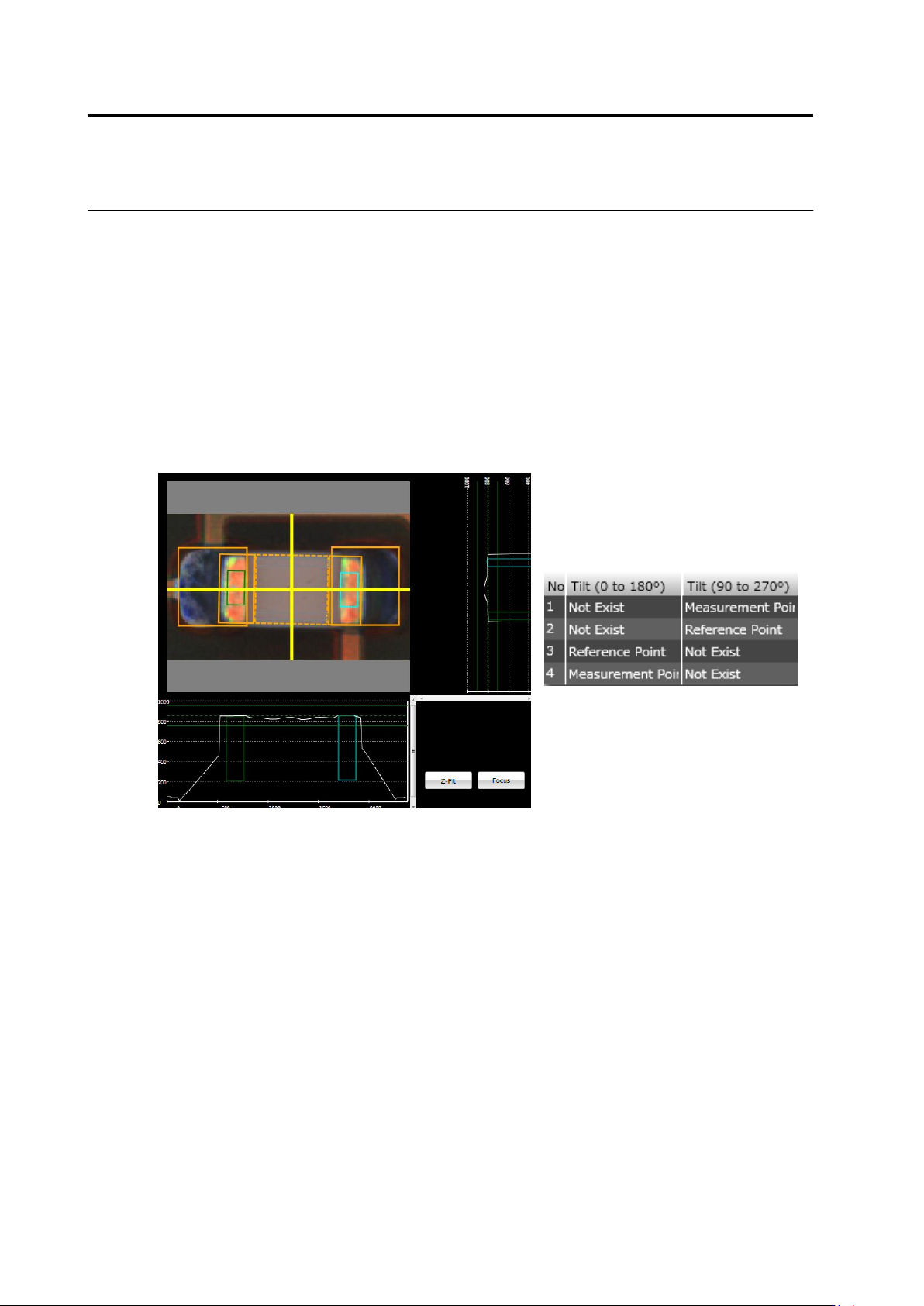
(1) Lifted Component Window
Specify a measurement range of height information used for the component height/lifted
component inspection. Use the mouse to edit the window position and size.
If the component tilt (0-180)/(90-270) is being selected, the lifted component window is
discriminated to reference point and measurement point. Described below are details.
Reference Point: Indicates a region as a height reference to measure the component tilt
(framed in yellow).
Measurement Point: Indicates a region to calculate a height from the reference point to
measure the component tilt (framed in light blue).
To change the reference point/measurement point setting, use the lifted component window
list.
2.15 Modifying an Inspection Program
2-167
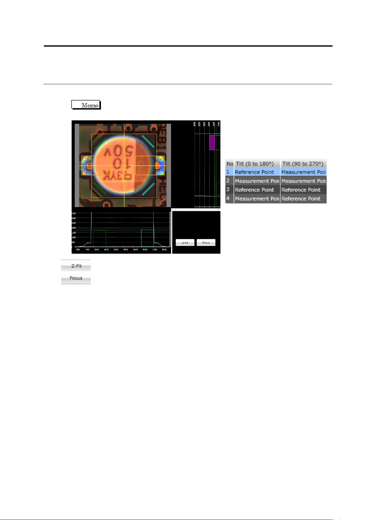
If a component type is electrolytic capacitor, the lifted component window is configured as
shown below.
Two component tilts are calculated in horizontal and vertical directions, and
averaged as inspection results.
Expands the Z scale by the maximum height.
Displays the selected window.
Chapter 2 Inspection Programming
2-168
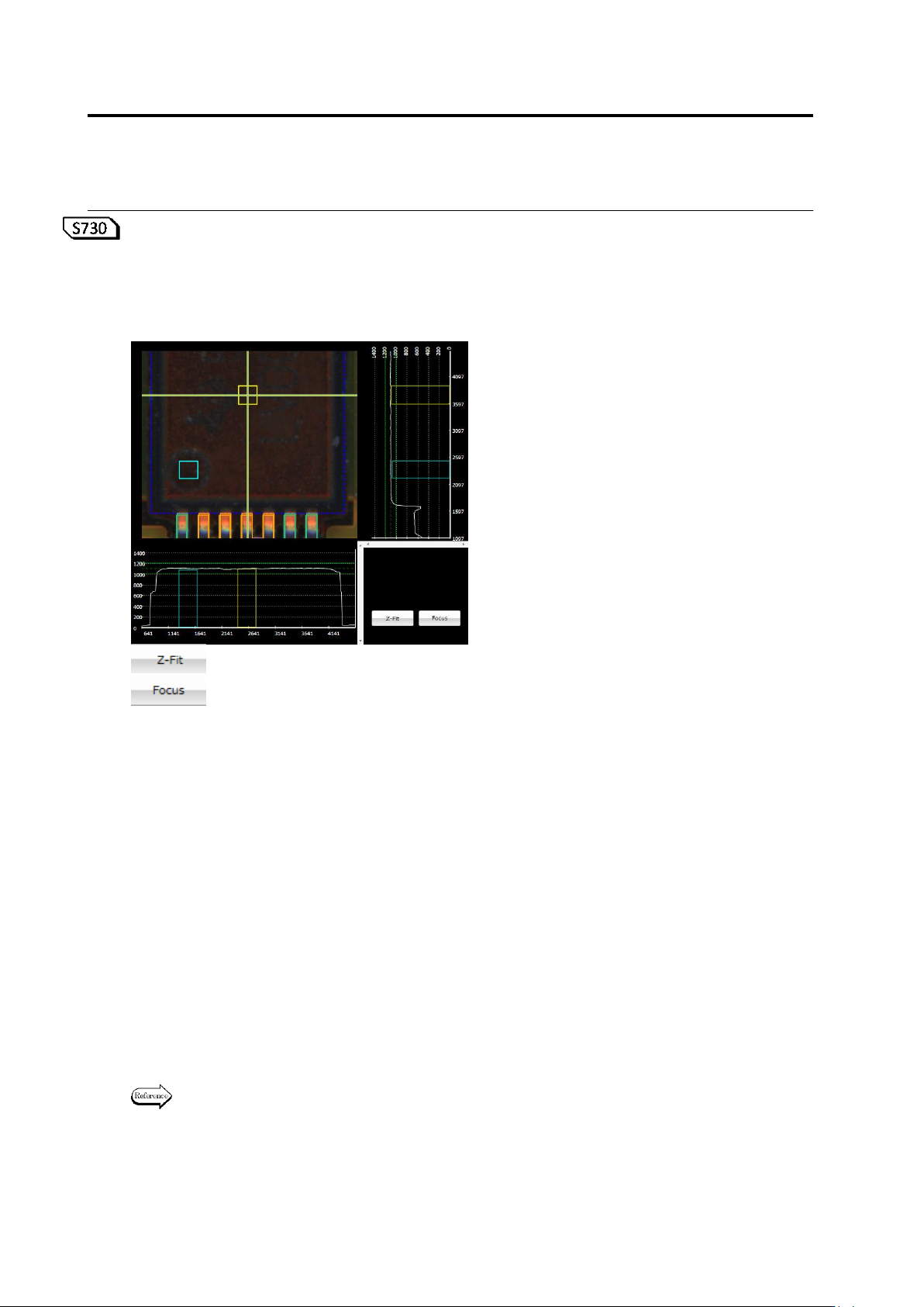
<Wrong Polarity/Height Inspection Edit Tool>
If wrong polarity/height inspection is being selected, the comparison area (reference point:
yellow) and polarity mark area (measurement point: light blue) are displayed in the wrong
polarity/height inspection edit tool. You can edit a position and/or size of the comparison and/or
polarity mark area to perform wrong polarity/height inspection.
: Z scale is extended based on the maximum height value.
: The selected window is displayed.
<Target Component (Recommended)>
- Other Chip:
An LED level difference is detected and the polarity inspection is performed.
- SOP, QFP, SOJ, QFJ, SON, QFN, connector, other lead component, other non-lead component,
other bottom electrode component, CSP, BGA
An embossed mark is detected and the wrong polarity inspection is performed.
① Comparison area (reference point: yellow)
Specify a measurement range of height information used for the wrong polarity/height
inspection. Use the mouse to edit the window position and size.
In X-Y, X-Z, and Y-Z diagrams, reference point window position (yellow rectangle) and
measured value of the reference point height are indicated as dashed lines and upper and
lower limits of the inspection criteria as continuous line.
② Polarity mark area (measurement point: light blue)
Specify a measurement range of height information used for the wrong polarity/height
inspection. Use the mouse to edit the window position and size.
In X-Y, X-Z, and Y-Z diagrams, measurement point window position (light blue rectangle) is
indicated.
For details of the inspection criteria and process, see Inspection Logic Manual, "3.4 Wrong
Polarity/Height".
①
②