Omron V-TS Teaching Manual.pdf.pdf - 第29页
2-2 2.11.1 Saving an Inspectio n Program ............................................................ 2- 118 2.11.2 Saving an Inspection Pro gram Under a New File Nam e .................... 2- 118 2.11.3 Releasing an Ins…

2-1
Chapter
2 Inspection Programming
2.1 Basics of Teaching ............................................................................................. 2-3
2.1.1 Basic Knowledge of Teaching ................................................................. 2-3
2.1.2 Configuration of the Editing Screen ...................................................... 2-10
2.1.3 Image Display Area Operation .............................................................. 2-17
2.2 Creating a New Inspection Program ................................................................ 2-25
2.3 Opening an Inspection Program....................................................................... 2-33
2.4 Registering for Inspection ................................................................................. 2-37
2.4.1 Registering Position Adjustment Marks ................................................ 2-38
2.4.2 Selecting Mount Data ............................................................................ 2-41
2.4.3 Mount Alignment ................................................................................... 2-46
2.4.4 Inspection Registration.......................................................................... 2-50
2.4.5 Component Registration ....................................................................... 2-53
2.4.6 Setting Component Number Group ...................................................... 2-75
2.5 Registering the Component Number Model .......................................................... 2-79
2.6 Specifying Inspection Criteria ........................................................................... 2-83
2.6.1 Criteria Setting (Product No.) ................................................................ 2-83
2.6.2 Criteria Setting (Individual Component) ................................................ 2-88
2.7 PCB/Component Block Unit Setting ................................................................. 2-91
2.7.1 Component Block Unit Setting .............................................................. 2-91
2.7.2 Mark Setting .......................................................................................... 2-95
2.8 PCB Testing/Result Check ............................................................................ 2-99
2.8.1 Testing Using PCBs .............................................................................. 2-99
2.8.2 Interpreting PCB Test Result .............................................................. 2-103
2.8.3 Saving Inspection Result..................................................................... 2-105
2.8.4 Displaying Inspection Detailed Result ................................................. 2-106
2.8.5 Modifying Inspection Criteria ............................................................... 2-107
2.9 Setting Oblique Inspection ............................................................................. 2-109
2.9.1 Setting Oblique Inspection Target Component Number ..................... 2-109
2.9.2 Setting Criteria for Oblique Inspection Items ...................................... 2-111
2.9.3 Specifying Oblique Inspection Component and Direction .............................. 2-113
2.9.4 Including Oblique Inspection in PCB Test........................................... 2-114
2.10 Setting Secondary Reflection Inspection ..................................................... 2-116
2.10.1 Setting a target component for the secondary reflection inspection ... 2-116
2.11 Saving an Inspection Program ..................................................................... 2-118

2-2
2.11.1 Saving an Inspection Program ............................................................ 2-118
2.11.2 Saving an Inspection Program Under a New File Name .................... 2-118
2.11.3 Releasing an Inspection Program ....................................................... 2-119
2.12 Reloading an Inspection Program ................................................................ 2-121
2.12.1 Reloading an Inspection Program Recently Used .............................. 2-121
2.12.2 Reloading Inspection Program Being Edited ...................................... 2-122
2.13 Outputting Inspection Coverage ................................................................... 2-123
2.14 Quitting Program Editing .............................................................................. 2-130
2.15 Modifying an Inspection Program ................................................................. 2-131
2.15.1 Modifying an Inspection Window ......................................................... 2-131
2.15.2 Changing Component and Electrode Information ............................... 2-133
2.15.3 Editing a Model .................................................................................... 2-135
2.15.4 Optimizing Boolean Expressions and Inspection Criterion Values ..... 2-169
2.15.5 Registering Visual Check Results ....................................................... 2-177
2.15.6 Replacing the Component Number ..................................................... 2-179
2.15.7 Changing the Component No. Name .................................................. 2-182
2.15.8 Setting up Destination ......................................................................... 2-184
2.16 Managing PCB Images .............................................................................. 2-187
2.16.1 Accessing the PCB Image Management Screen ................................ 2-187
2.16.2 Deleting a PCB Image ......................................................................... 2-189
2.16.3 Editing Models by the Unit of PCB ...................................................... 2-191
2.16.4 Editing a Reference Level Model ........................................................ 2-193
2.16.5 Changing Brightness of PCB Image ................................................... 2-205
2.16.6 Cache Setting ...................................................................................... 2-206
2.16.7 Deleting Cache .................................................................................... 2-207
2.17 Mass-Produced PCB Image ......................................................................... 2-208
2.18 Inspection Program Maintenance ................................................................. 2-212
2.18.1 Saving an Inspection Program ............................................................ 2-213
2.18.2 Reading an Inspection Program .......................................................... 2-215
2.18.3 Updating Inspection Program .............................................................. 2-217
2.18.4 Deleting an Inspection Program .......................................................... 2-218
2.18.5 Renaming an Inspection Program ....................................................... 2-219
2.18.6 Copying an Inspection Program .......................................................... 2-220
2.18.7 Outputting Content of Inspection Program List ................................... 2-221
2.18.8 Verifying Inspection Program Data ..................................................... 2-224
2.1 Basics of Teaching
2-3
2.1 Basics of Teaching
This section describes the basics of teaching using v-TS.
2.1.1 Basic Knowledge of Teaching
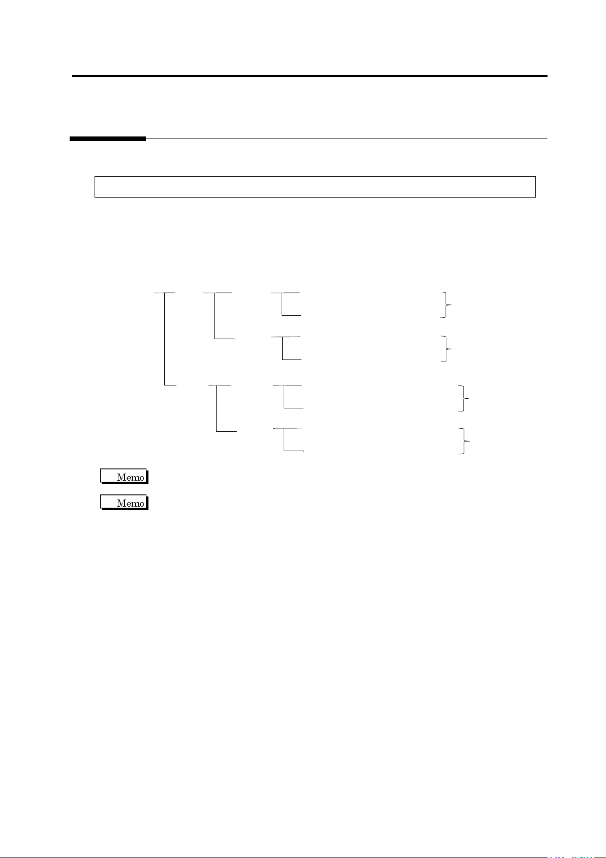
Inspection Programs
A set of inspection programs for individual processes (Z: Mount, and S: Reflow), PCB surfaces
(top or bottom) and destinations are required.
PCB Name:
AAA
Top
Bottom
Inspection Program: Z_TOP_0001
Destination
Mount
Process
Reflow
Process
Inspection Program: Z_TOP_0002
Inspection Program: Z_BOTTOM_0001
Mount
Process
Reflow
Process
Inspection Program: Z_BOTTOM_0002
Inspection Program: S_TOP_0001
Destination
Inspection Program: S_TOP_0002
Inspection Program: S_BOTTOM_0001
Inspection Program: S_BOTTOM_0002
Destination
Destination
v-TS only supports the creation of inspection programs for the implementation and reflow
processes.
"Destination" here refers to the variations of PCBs including different components or component
numbers, which go through the same printing process. Due to the difference of mounting
configuration, different inspection programs are required and teaching must be performed
separately.
To set up destination, refer to Section 2.15.8 “Setting up Destination.”