Omron V-TS Teaching Manual.pdf.pdf - 第70页
2.4 Registeri ng f or Insp ection 2- 43 W hen other user is editing the format, the dialog be low appears indicating you cannot edit it. ■ Format Name Enter the form at name within 32 sing le-b yte alphanumeric character…
Chapter 2 Inspection Programming
2-42
2.
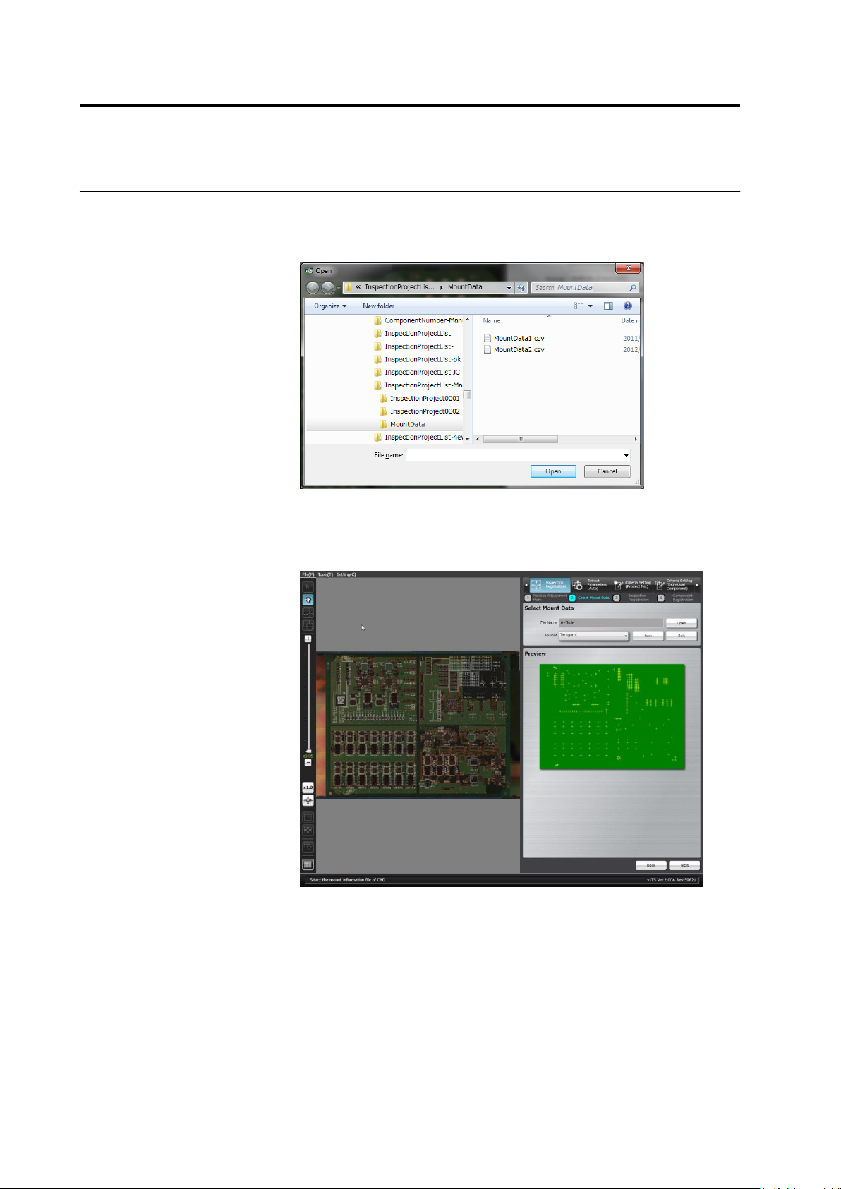
The file selection dialog appears.
Specify the mount data file and click [Open].
Files with any extension can be read because there is no limitation
of extension.
3.
Select the format to display the data.
A map showing the positions of components is displayed in the
preview area when an appropriate format is selected for the mount
data.
If no corresponding format is available, click [New] or [Edit] to create
the format.
2.4 Registering for Inspection
2-43
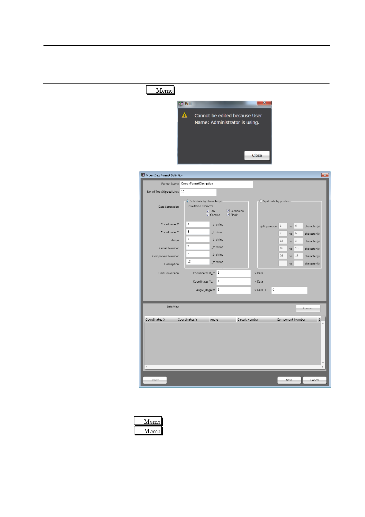
When other user is editing the format, the dialog below
appears indicating you cannot edit it.
■ Format Name
Enter the format name within 32 single-byte alphanumeric
characters/symbols.
Symbols that can be used: ! # $ % & ' ( ) - = ^
~
@` [ { ;+ } ] ,._␣
Both upper and lower case alphabet characters can be used.
However, they are not distinguished.
■ No. of Top Skipped Lines
Enter the number of lines counting from the top, which must be
skipped to avoid the loading of unnecessary information from the
mount data file.
Chapter 2 Inspection Programming
2-44
■ Data Separation
Specify the method of delimiting the data.
Mount data must be separated into the six items including X
coordinate, Y coordinate, angle, circuit number, component
number, and explanation.
Explanation is not indispensable. Specify it arbitrarily.
Split data by character(s)
The data is separated by the specified delimiting character.
Specify the delimiting character and the ordinal number of
the delimiter (nth string) where each data item starts.
Split data by position
The data is separated into sets of the specified numbers of
characters.
Specify the ordinal numbers of the characters (from n to n +
the number of characters) where each item starts and ends.
■ Unit Conversion
Convert the unit of the X and Y coordinates of the mount data
from mm (if it is used) to μm by multiplying the value by 1000
(1000 x Data). The angle must be converted to the value in the
counterclockwise direction (-1 x Data + 0) if it is represented in the
clockwise angle.
Values up to 8 digits and 3 decimal places either in positive and
negative numbers can be entered.
■ Data View
Check if the individual data items are separated correctly.
Click [Preview] to display the data separation view obtained by
the setting.
The coordinate values are rounded at the 4th decimal place.
The angle is represented in 0 to 359 degrees, with the decimal
1st place rounded. A value exceeding 360 degrees or negative
value is converted to the value in 0 to 359 degrees.
The alphabets in the circuit number and component number are
expressed in upper case letters.
The effective numbers of characters for the circuit number and
component number are up to 16 and 64 characters respectively.
If the numbers exceed the limits, an error dialog appears and no
data is displayed for the items in the data view.
The symbols that can be used for the circuit number and
component number are as follows:
! # $ % & ' ( ) - = ^
~
@` [ { ;+ } ] ,._
␣
If the symbols not allowed (¥|:*<>/?) are used, the data view
displays no data for the item. If a slash is used, it will be
converted to a hyphen (-). The quotation marks (") at the head
and end of the entire string are ignored and only the string is
displayed. However, if the mark is used inside the string, no data
is displayed for the item in the data view.
Click [Save]. The format setting is saved and the dialog is closed.
Clicking [Cancel] aborts the setting and closes the dialog.
Click [Delete] to delete the format being edited and close the dialog.