Omron V-TS Teaching Manual.pdf.pdf - 第180页
2.15 M odifying an Inspection Pr ogram 2- 153 Target Model set 1 Model set 2 At registration of Ite m N o . Wrong font Wrong layout Color of letter dimmed (Wrong binary threshold) At registration of Ite m N o . Wrong fon…
Chapter 2 Inspection Programming
2-152
<Model Image Editing Tools>
The model image edit tool is displayed when component difference/polarity difference inspection
is selected.
Use the tools to edit the binarized areas or colors in the model image for character or symbol
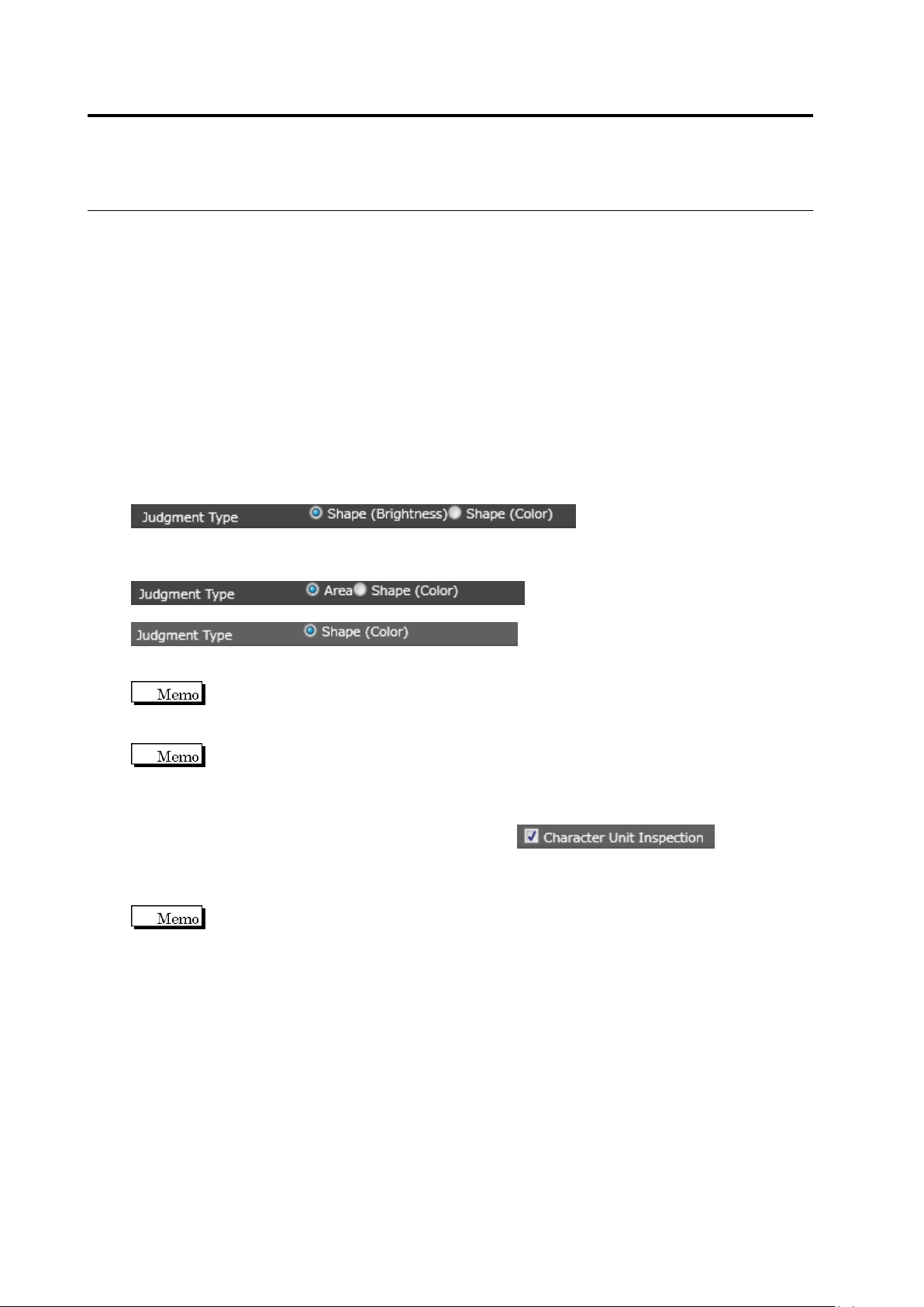
extraction. Model image can be judged in three ways:
Area (Color): Color is adjusted to judge component difference.
Shape (Brightness): Binarization area is specified and brightness is adjusted to judge the
pattern.
Shape (Color): Binarization area is specified and color is adjusted to judge the pattern.
To judge a model image, check the display corresponding the setting of “Component has
character pattern” of the component number:
Component has character pattern: ON
Select a judgment type for component difference/polarity difference inspection
Component has character pattern: OFF
Select a judgment type for component difference inspection
Select a judgment type for polarity difference inspection
For the polarity difference inspection, you cannot select [Area (Color)] as the
matching rate is judged based on the model asymmetry.
If color difference is small between the component body and character patterns,
whether characters or patterns can be judged easily by enabling the “Component Top Highlight
Display” option.
For calculation or measured value by character, enable to calculate
the measured value per mask area and perform the component difference inspection. The
measure value is calcurated with the condition that the mask area with no pixel to the left, right,
top, or bottom side is regarded as a single unit.
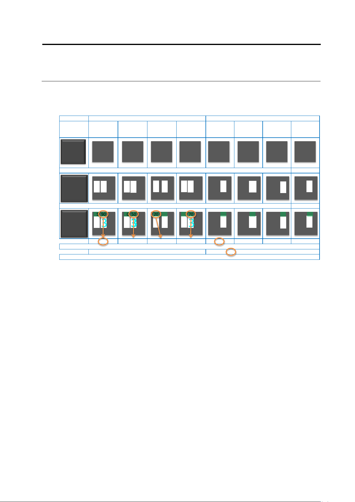
Shown below is an example.
2.15 Modifying an Inspection Program
2-153
Target Model set 1 Model set 2
At registration of Item No.
Wrong font Wrong layout
Color of letter
dimmed
(Wrong binary
threshold)
At registration of Item No.
Wrong font Wrong layout
Color of letter
dimmed
(Wrong binary
threshold)
Set masking so that the mask area is independent for each character by "inspection by character" ON
Perform measurement by character, and regard the worst value in the model as a representative of the model
90 50 20 70 85 55 30 70
Regard the best value in the model set as the representative of the model set
90 85
Regard the worst value as the representative of inspection between the model sets, and perform go/no-go judgment compared to the test specification.
1 313
13B 13 13 1 3 13 B B
B
B
13B
13 13 B B
B
B
1 313
13B
13 13 B B
B
B
95 90 60 50 20 90 75 70 85 55 30 70
Chapter 2 Inspection Programming
2-154
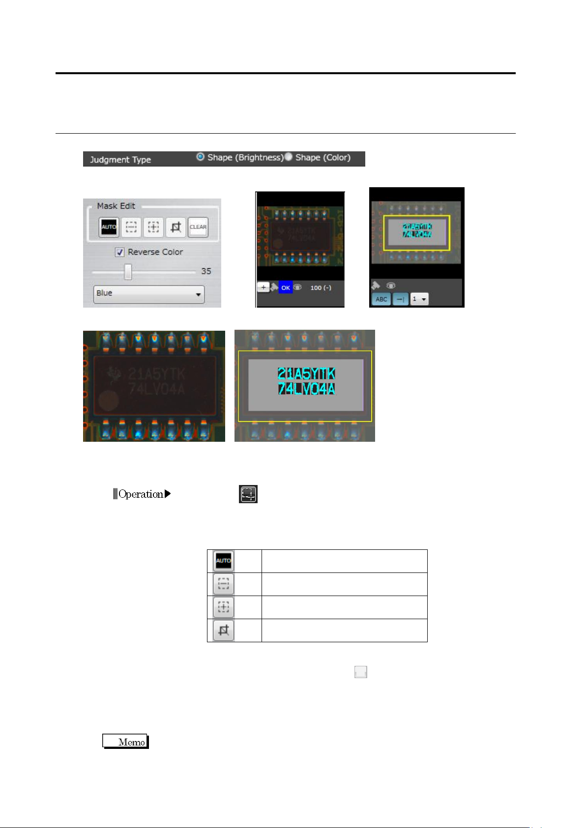
Judgment Type: Shape (Brightness)
Editing Tools PCB Test Result/Mass Production Image, Model Mask Model
Mask Model Image (Image including component and electrode).
(1) Mask Area
Specify the area to mask in the model image.
1.
Click (Create Window) button in the Image Operation tool bar.
Drag and drop the cursor to form a rectangle in the model image.
2.
Click either of the buttons below to specify the area to mask in the
model image.
Automatically set the mask per
character and mark.
Mask the area inside the drawn
rectangle.
Enables the area inside the drawn
rectangle.
Mask the area outside the drawn
rectangle.
3.
Repeat the above procedure to specify multiple areas to mask.
To clear the masked areas, click .
(2) Extraction Area Ratio
Specify the ratio (%) of the pixels to binarize (for extraction) to the entire unmasked area
(100%). The pixels of the color specified in (3) are extracted starting from those with the
lower brightness or saturation, until the specified extraction ratio is reached.
The ratio can be specified in the range of 1 to 99.
Operation
(1)
(4)
(2)
(3)
(7)
(6)
(5)