Omron V-TS Teaching Manual.pdf.pdf - 第73页
Chapter 2 Inspecti on Programm ing 2- 46 2.4.3 Mount Al ignment Align the coordinates of individual com ponents in the m ount data (loaded in the p revious section) to the PCB im age. 1. The mount positions s hown by &qu…
Chapter 2 Inspection Programming
2-46
2.4.3 Mount Alignment
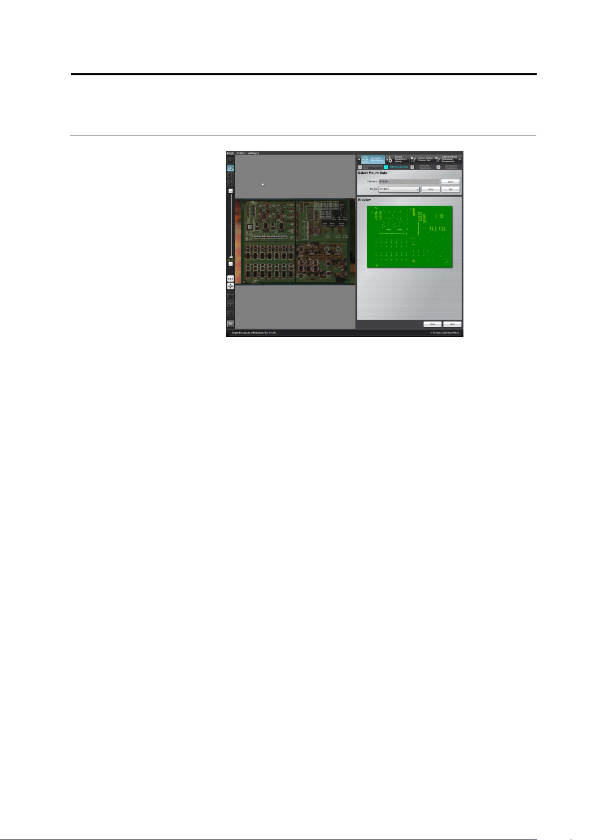
Align the coordinates of individual components in the mount data (loaded in the previous section)
to the PCB image.
1.
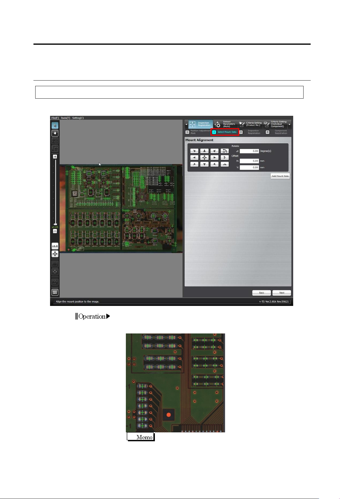
The mount positions shown by "+" marks are overlaid on the PCB
image. Use the buttons or the mouse to align the "+" marks at the
centers of the corresponding components on the PCB image.
For precise alignment, enlarge the PCB image and shift the
field of vision to check that "+" marks are also aligned at the
centers of the corresponding components in a different field of
vision.
Operation
2.4 Registering for Inspection
2-47
◆
Adjustment Using the Mouse
Click the Select Window button in the Mouse toolbar and drag the
mount data to align the "+" marks to the centers of corresponding
components.
◆
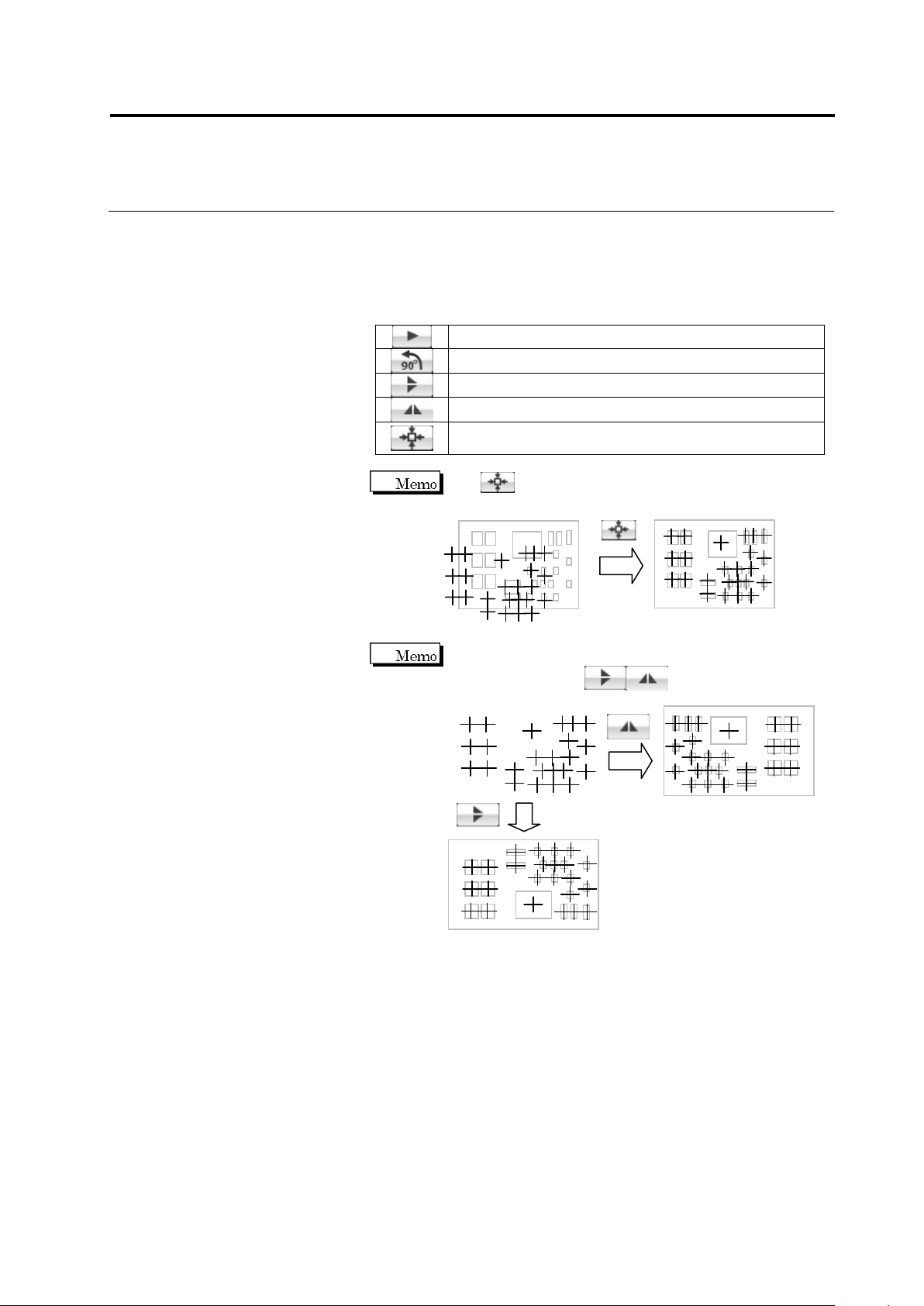
Adjustment Using Buttons
Move the mount data in the arrow direction.
Rotate the mount data by 90 degrees counterclockwise.
Vertically reverse the mount data.
Horizontally reverse the mount data.
Align the center of the mount data at the center of the
PCB image.
Use to align the centers of the mount data and PCB
image if the position deviation is large.
If the mount data uses a different coordinate system from
the PCB image, click to reverse the mount
positions before position alignment.