Omron V-TS Teaching Manual.pdf.pdf - 第85页
Chapter 2 Inspecti on Programm ing 2- 58 If you select auto calculation, you cannot enter a component height manually. To register the central value of the component height as the result of the PCB test to the component …
2.4 Registering for Inspection
2-57
To correct the angle, click several times. To rotate all the
components of the same component number at the same time, use
the [Rotate All] checkbox, then specify the degrees.
To perform fine adjustment of the angle, directly enter the angle
value.
The [Show Model] checkbox is disabled for a new component
number.
Enter an angle from 0 to 359.9 degrees.
If [Rotate All] is selected, angle adjustment by a direct entry is
effective for only the displayed components.
6.
Specify if the component has the letter or symbol marking in the
check box.
The letters or symbol marks refer to the color and shape of the
letters or marks attached to the component/polarity, and
different inspection logic is required for those with the letter or
symbol marks.
For a chip resistor with a size of 1005 or less, a Component
Window is created without character/symbol mark
automatically.
Refer to the Inspection Logic Manual, "3.2 Right Component" for
details on the inspection for a right component.
7.
Specify options for component difference inspection, and polarity
difference inspection in the check boxes.
No check box is selected by default for all component types.
8.
Specify if oblique inspection is performed in the check box.
Oblique inspection cannot be specified to "Yes", if "BGA/CSP" or
"Others (Bottom Electrode)" is selected for the component type.
Refer to "2.9 Setting Oblique Inspection" for the details of
oblique inspection.
9.
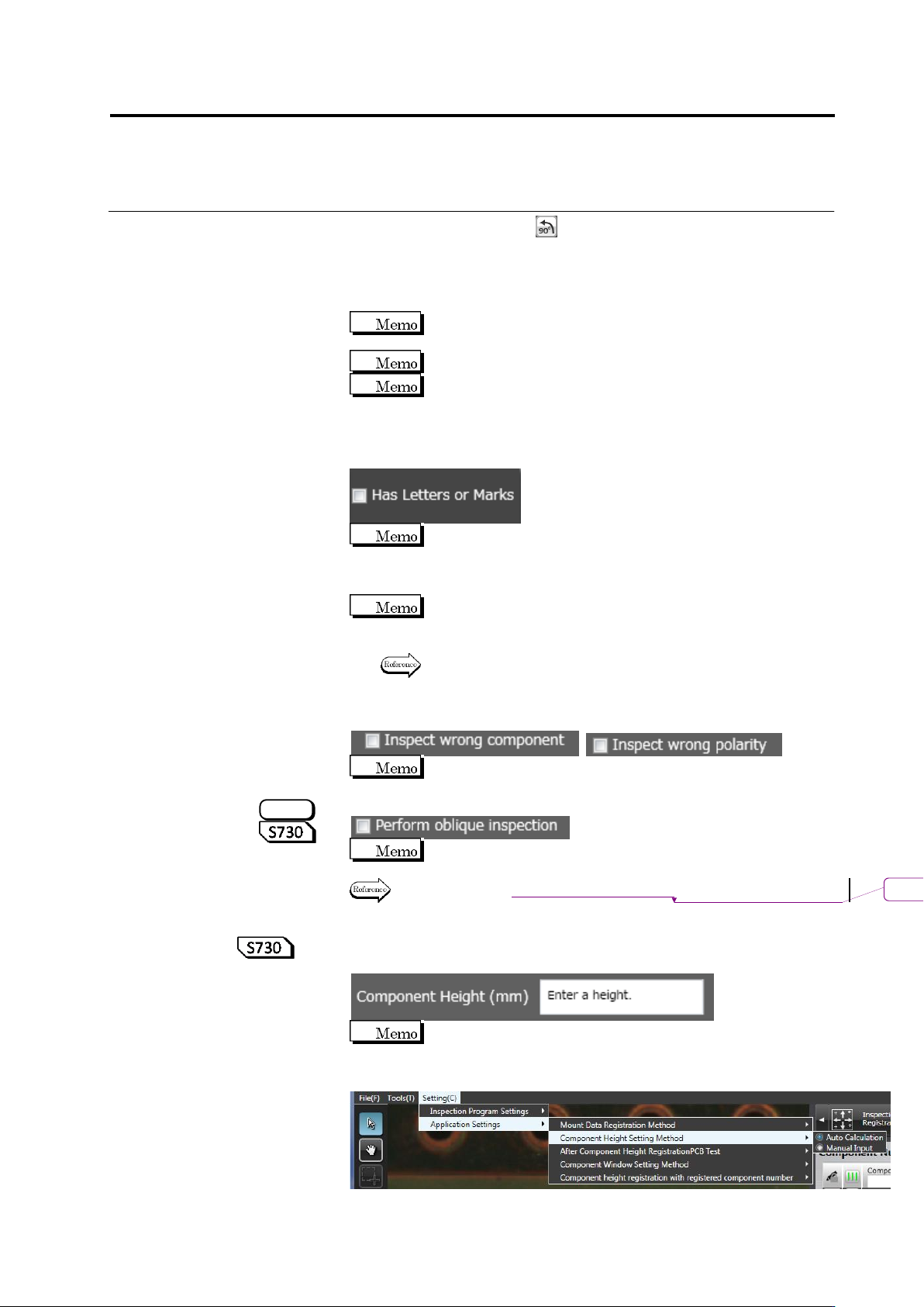
Specify a component height. Enter a component height in a
numeric value or 0.1mm or larger.
To automatically calculate a component height upon learning
instead of manual input, select Setting (C) - Component Height
Setting Type - Automatic Calculation.
S720A
削除
: Setting Oblique Inspection
Chapter 2 Inspection Programming
2-58
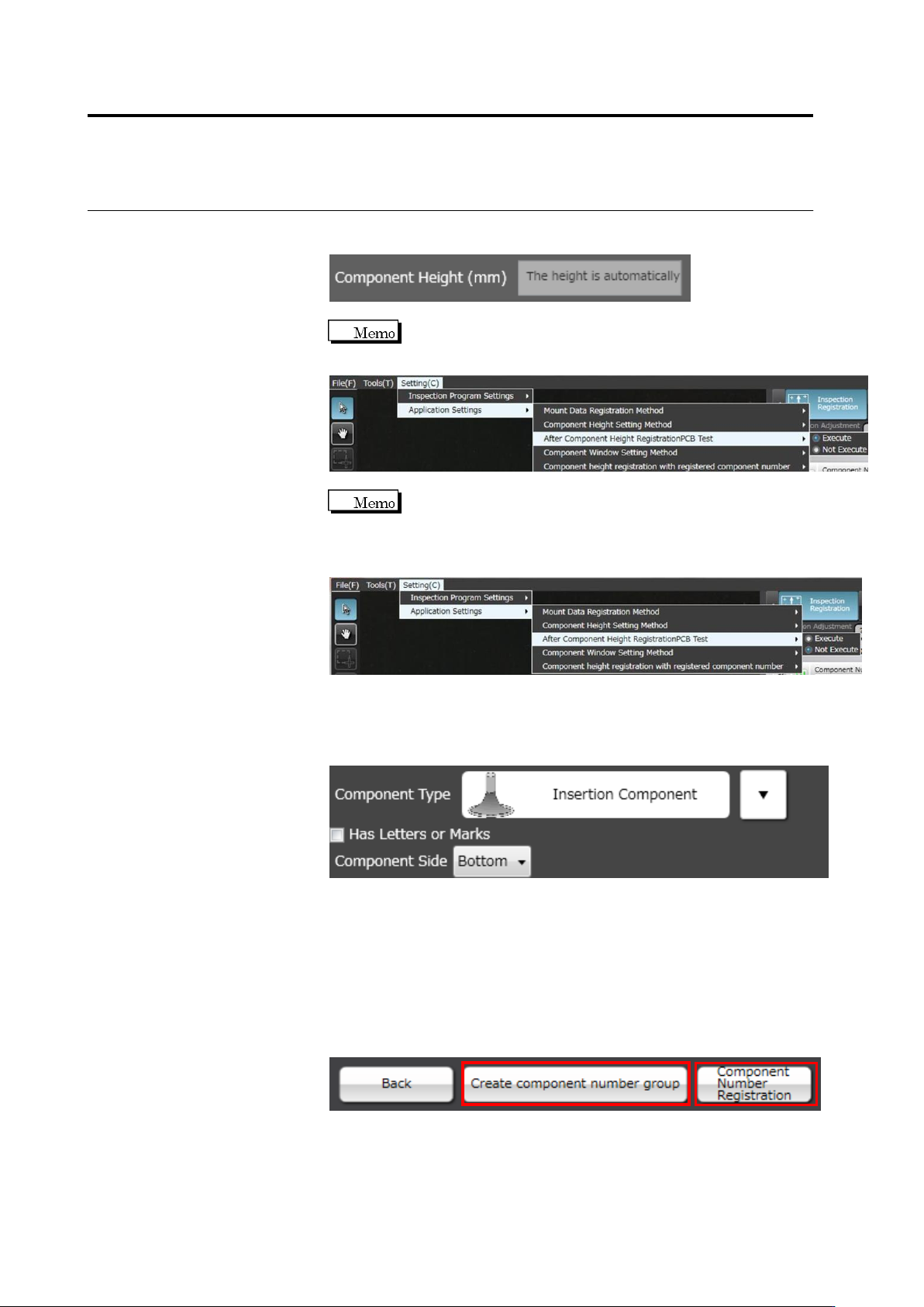
If you select auto calculation, you cannot enter a component height
manually.
To register the central value of the component height as the
result of the PCB test to the component number, select After
Component Height Registration PCB Test to [Execute].
If you select [Not Execute] for Component height registration
with registered component number, the height registration to
the already registered component number can be skipped. If
you do not need to change the height criteria, select [Not
Execute].
10.
If "Insertion Component" is selected, select the component surface
in the list box.
"Top" refers to the side where components bodies are seen, and
"Bottom", the side with inserted leads.
11.
Click [Next] to proceed to the Land Setting screen.
If you select "BGA/CSP" or "Others(Bottom Electrode)" for the
component type, [Component Number Registration] will appear
instead of [Next] as settings after land settings are not required.
Click [Component Number Registration] and set other unregistered
component numbers. To create a component number group based
on the configured component number, click [Create component
number group]. Component number registration is performed at the
same time.
2.4 Registering for Inspection
2-59
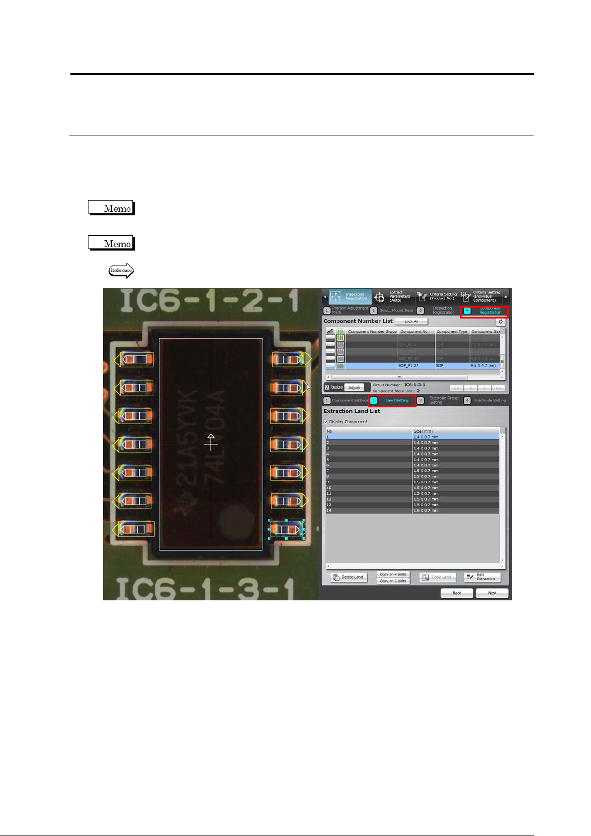
2.4.5.2 Land Setting
Land windows are automatically extracted and displayed on the screen, if they are not specified
for the component yet, based on the bare PCB image. The size and position of the auto-extracted
land windows can be adjusted on the screen.
You cannot select the target component on the land settings screen. To change the component,
click [Back] to return to the component settings screen and select a component, adjust the
Component Body Window, and then click [Next].
Land windows must be manually added or deleted, if the auto extraction failed (due to the wrong
number of land windows).
Refer to “Add a land window” or “Delete a land window” of “2.4.5.2 Land Setting” for the
procedures to add or delete land windows.