Omron V-TS Teaching Manual.pdf.pdf - 第287页
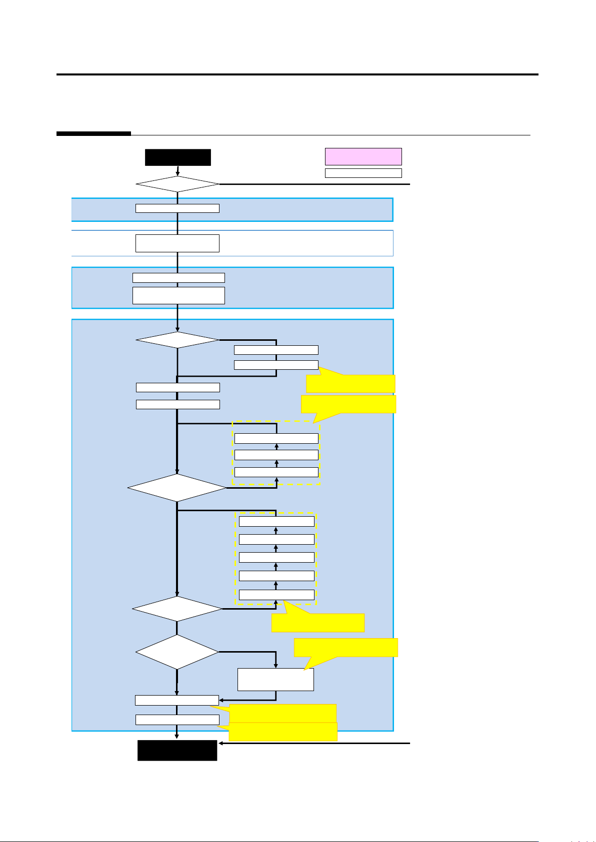
Appendix 4. Mass Pro duction Adjustm ent (false call zero) a- 10 Appendix 4. Mass Production Adjustment (false call zero) Result confirmation screen Criteria setting (com p. No.) screen Machine Mass production Real fault…
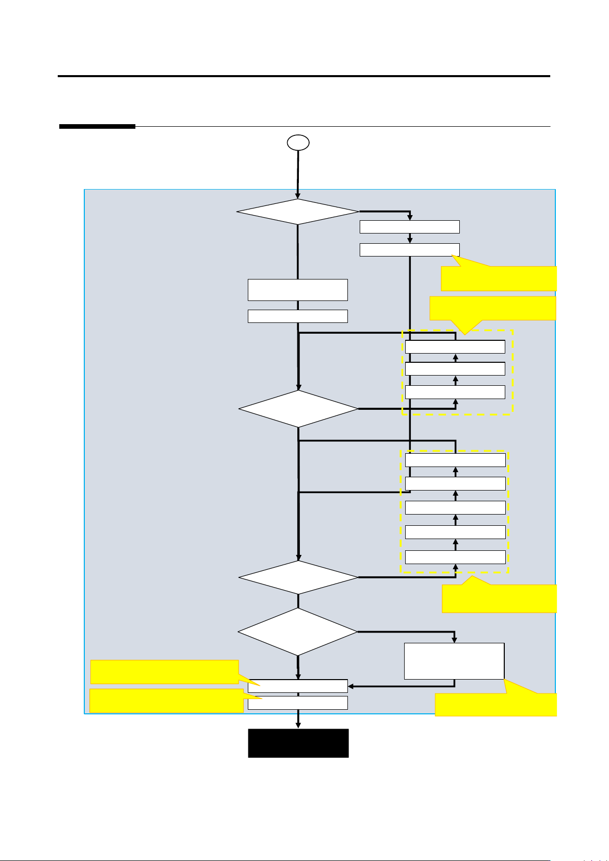
Appendix 3. Mass Production Adjustment (false call minimization)
a-9
Criteria setting (comp. No.) screen
Mass production
adjustment completed
Register images
Ye
No
Register actual faults
Execute comp./
Confirm fault name
Adjust characteristic
Yes
Optimization
Adjust characteristic
parameters of applicable
insp. item
Yes
N
N
Adjust W position, W
Set exclusion window
Is there comp./electrode
height offset?
Adjust comp. height
Set comp. tilt
Adjust electrode height
Adjust lifted window
Adjust lifted window
Yes
N
Land error
Refer to [Appendix 5. Real
Fault Registration Procedure]
1
Refer to [Appendix 10. Inspection
Criteria Setting].
Refer to [Appendix 9. Land
Inspection Adjustment Procedure]
Refer to [Appendix 7. Position
Correction/Extraction]
Refer to [Appendix 9. Land Inspection
Adjustment Procedure].
Refer to [Appendix 8. Height
Information Setting]
Unregistered actual fault?
Extraction offset on each
W?
Undetected fault and false
call insp. items can be
Appendix 4. Mass Production Adjustment (false call zero)
a-10
Appendix 4. Mass Production Adjustment (false call zero)
Result confirmation screen
Criteria setting (comp. No.) screen
Machine
Mass production
Real fault?
Yes
No
Move to criteria setting
Test PCB (adjustment image)
Register real faults
Register images
Undetected
Save as adjustment
Execute inspection
(Adjustment mode for
Yes
No
Confirm real fault name
Execute comp./comp. No.
Yes
Optimization
Adjust characteristic
parameters of applicable
Yes
No
No
Adjust characteristic
Adjust W position, W size
Set exclusion W
Is there comp./electrode
height offset?
Yes
No
Land error
Refer to [Appendix. 5 Real
Fault Registration Procedure].
Refer to [Appendix 8. Height
Information Setting]
Refer to [Appendix 10. Inspection
Criteria Setting].
Refer to [Appendix 9. Land
Inspection Adjustment Procedure]
Refer to [Appendix 9. Land
Inspection Adjustment Procedure].
Automatic (internal)
Manual operation
Refer to [Appendix 7. Position
Correction/Extraction]
Extraction offset on each
W?
Adjust comp. height
Set comp. tilt
Adjust electrode height
Adjust lifted window
Adjust lifted window
Can characteristic
parameters be editd for
Insp. program release
(mass production
Appendix 5. Real Fault Registration Procedure
a-11
Appendix 5. Real Fault Registration Procedure
Register real fault using the procedure below.
1. Select the “Criteria Setting (Component Number)” tab.
2. Select a component number with which a visual inspection result is registered from the
component number list, and click [Model Editing].
3. Select a thumbnail image with which you wish to enter a visual inspection result from the
component thumbnail image list, and select a visual inspection result from the pull-down of
visual inspection results of window configuration. If more than one window is selected, the same
visual inspection result is registered in all the selected windows of the same type.
4. To go on to enter visual inspection results in the other thumbnail images, repeat step 3.
For details of real fault registration, refer to P2-162 Section 2.15.5 “Registering Visual Check
Results.”
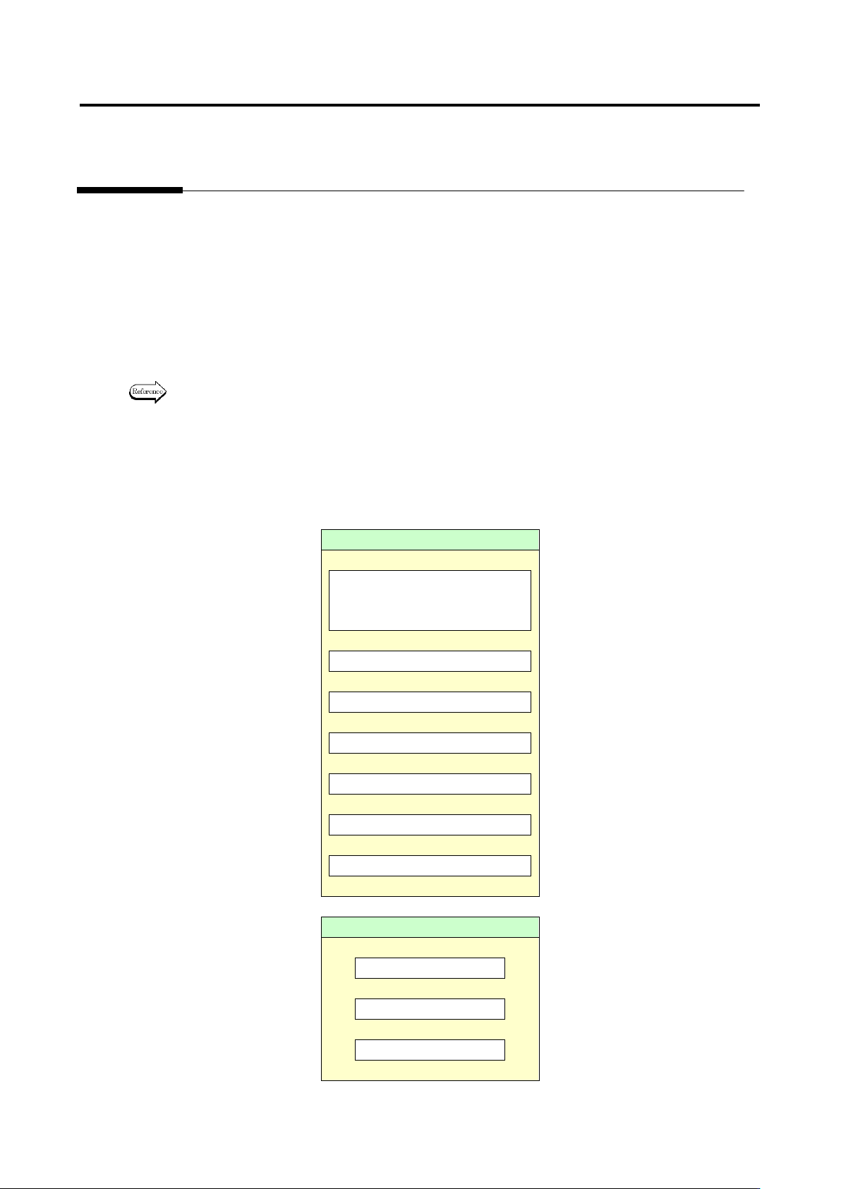
In optimization, fault detection is made in order of priority: (1) component, (2) electrode and (3) land. In
the case where both component and electrode are faulty, the system judges that the fault has been
detected as long as the component is judged as fault so that it does not detect the electrode fault. If the
electrode has been judged as fault, the visual inspection result is registered as the detected inspection
item name if there is no problem on the judgment.
Component
Missing component
* Including lifted component
and component breakage
↓
Component difference
↓
Polarity difference
↓
Upside down
↓
X position gap
↓
Y position gap
↓
Component skew
↓
Electrode
Side overhang
↓
End overhang
↓
End overlap