Omron V-TS Teaching Manual.pdf.pdf - 第331页
Appendix 9. Land Insp ection Adjustm ent Procedure a- 54 Inspection item 8. Land error Based on th e color which was detected in the land windo w and do es not appear in norm al cases , inspect if there is an error on th…
Appendix 9. Land Inspection Adjustment Procedure
a-53
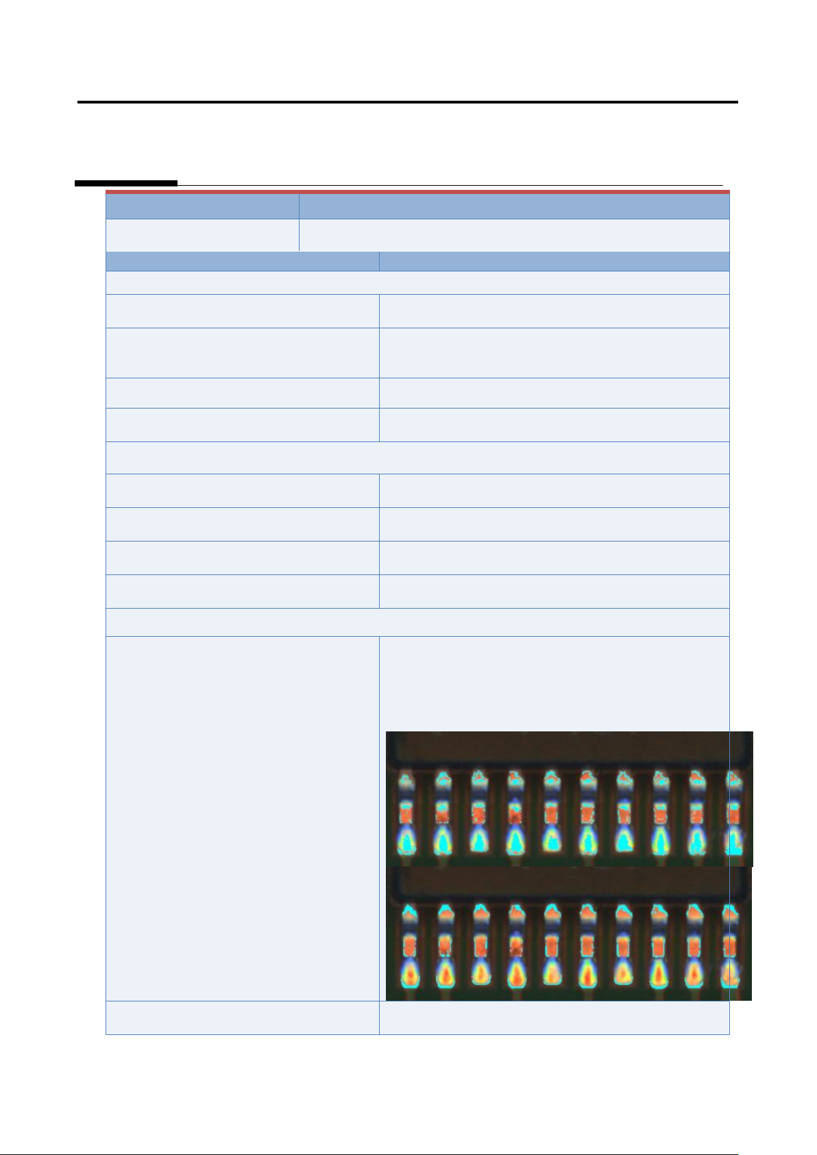
Inspection result
Component image (PCB test)
Normal (land exposure
overlooked)
(*Image to be pasted)
Cause
Confirmation/repair method
When position does not match between the actual land and extracted land:
The land window is not positioned
appropriately.
Refer to Appendix 7.2.
The land window of the peripheral
components of the applicable component
is not positioned appropriately.
Refer to Appendix 7.2.
The fiducial correction is not appropriate.
Refer to Appendix 7.1.
The position correction color is not
appropriate.
Refer to Appendix 7.2.
When position does not match between the actual component (electrode) and extracted component
(electrode):
The component extraction is not
positioned appropriately.
Refer to Appendix 7.5.
The electrode tip extraction is not
positioned appropriately.
Refer to Appendix 7.7.
The electrode side is not extracted in an
appropriate position.
Refer to Appendix 7.6.
The electrode window is not sized
appropriately.
Refer to Appendix 7.5.
The land exposure color is not set
appropriately.
1) Move to the “Criteria Setting” tab.
2) Select “Inspection Criteria” - “Land Exposure”, and
click the [Model Editing] button (*Image to be pasted).
3) Edit characteristic parameters using the color table
editing tool so that metal portion of the land (such as
copper foil) is extracted.
The inspection criteria are not set
appropriately.
Refer to Appendix 10.1.
Appendix 9. Land Inspection Adjustment Procedure
a-54
Inspection item 8. Land error
Based on the color which was detected in the land window and does not appear in normal cases,
inspect if there is an error on the land.
If false call or overlooking still remains in the inspection result, “Land error” is displayed.
The inspection result image, cause, and repair method of land error are as follows:
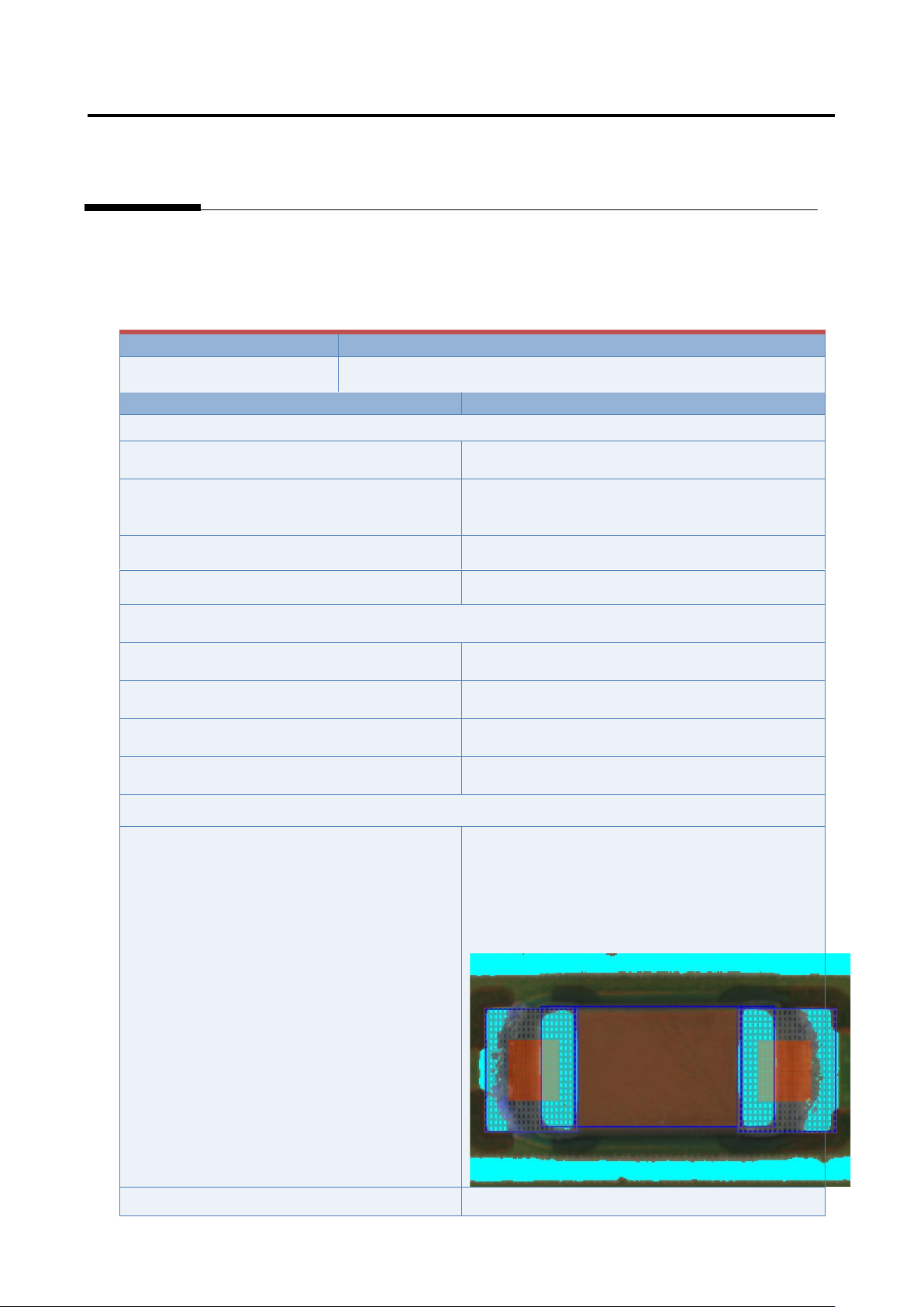
Inspection result
Component image (PCB test)
Land error
Cause
Confirmation/repair method
When position does not match between the actual land and extracted land:
The land window is not positioned
appropriately.
Refer to Appendix 7.2.
The land window of the peripheral components
of the applicable component is not positioned
appropriately.
Refer to Appendix 7.2.
The fiducial correction is not appropriate.
Refer to Appendix 7.1.
The position correction color is not appropriate.
Refer to Appendix 7.2.
When position does not match between the actual component (electrode) and extracted component
(electrode):
The component extraction is not positioned
appropriately.
Refer to Appendix 7.5.
The electrode tip extraction is not positioned
appropriately.
Refer to Appendix 7.7.
The electrode side is not extracted in an
appropriate position.
Refer to Appendix 7.6.
The electrode window is not sized
appropriately.
Refer to Appendix 7.5.
The inspection area of land error is not
appropriate.
1) Move to the “Criteria Setting” tab.
2) Select “Inspection Criteria” - “Land Exposure”,
and click the [Model Editing] button (*Image to be
pasted).
3) Edit characteristic parameters using the color
table editing tool so that metal portion of the land
(such as copper foil) is extracted.
The inspection criteria are not set appropriately.
Refer to Appendix 10.1.
Appendix 9. Land Inspection Adjustment Procedure
a-55
Inspection result
Component image (PCB test)
Normal (land error
overlooked)
Cause
Confirmation/repair method
When position does not match between the actual land and extracted land:
The land window is not positioned
appropriately.
Refer to Appendix 7.2.
The land window of the peripheral
components of the applicable component is
not positioned appropriately.
Refer to Appendix 7.2.
The fiducial correction is not appropriate.
Refer to Appendix 7.1.
The position correction color is not
appropriate.
Refer to Appendix 7.2.
When position does not match between the actual component (electrode) and extracted component
(electrode):
The component extraction is not positioned
appropriately.
Refer to Appendix 7.5.
The electrode tip extraction is not positioned
appropriately.
Refer to Appendix 7.7.
The electrode side is not extracted in an
appropriate position.
Refer to Appendix 7.6.
The electrode window is not sized
appropriately.
Refer to Appendix 7.5.
The inspection area of land error is not
appropriate.
1) Move to the “Criteria Setting” tab.
2) Select “Inspection Criteria” - “Land Exposure”,
and click the [Model Editing] button (*Image to be
pasted).
3) Select the fault component, click the * button, and
select the area in which the characteristic of the fault
appears large.
4) Click the * button, and select the area in which the
characteristic of the fault does not appear (*Image to
be pasted).
The land error color is not set appropriately.
1) Move to the “Criteria Setting” tab.
2) Select “Inspection Criteria” - “Land Exposure”,
and click the [Model Editing] button (*Image to be
pasted).
3) Select the fault component and edit characteristic
parameters using the color table editing tool so that
the color of the fault is extracted (*Image to be
pasted).
The inspection criteria are not set
appropriately.
Refer to Appendix 10.1.