Omron V-TS Teaching Manual.pdf.pdf - 第31页
Chapter 2 Inspection Programm ing 2-4 Teaching Flow 1) New creation Shoot raw PCBs an d inspection PCBs using the PCB inspection s y s t em 4) Set up the criterio n 5) Set up PCB and component block ID 2) Register insp…
2.1 Basics of Teaching
2-3
2.1 Basics of Teaching
This section describes the basics of teaching using v-TS.
2.1.1 Basic Knowledge of Teaching
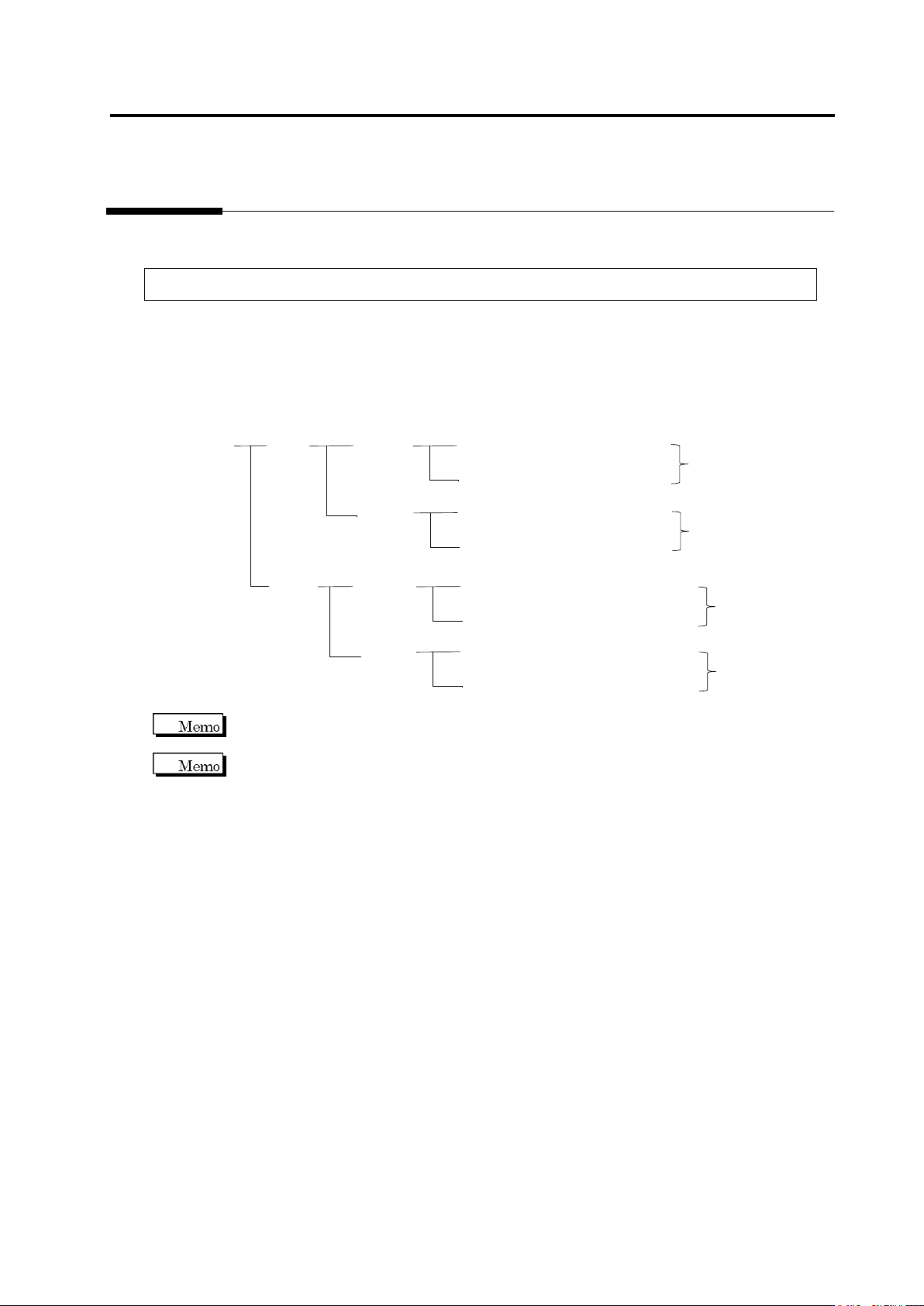
Inspection Programs
A set of inspection programs for individual processes (Z: Mount, and S: Reflow), PCB surfaces
(top or bottom) and destinations are required.
PCB Name:
AAA
Top
Bottom
Inspection Program: Z_TOP_0001
Destination
Mount
Process
Reflow
Process
Inspection Program: Z_TOP_0002
Inspection Program: Z_BOTTOM_0001
Mount
Process
Reflow
Process
Inspection Program: Z_BOTTOM_0002
Inspection Program: S_TOP_0001
Destination
Inspection Program: S_TOP_0002
Inspection Program: S_BOTTOM_0001
Inspection Program: S_BOTTOM_0002
Destination
Destination
v-TS only supports the creation of inspection programs for the implementation and reflow
processes.
"Destination" here refers to the variations of PCBs including different components or component
numbers, which go through the same printing process. Due to the difference of mounting
configuration, different inspection programs are required and teaching must be performed
separately.
To set up destination, refer to Section 2.15.8 “Setting up Destination.”
Chapter 2 Inspection Programming
2-4
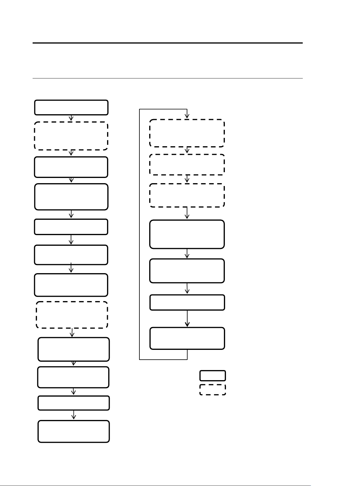
Teaching Flow
1) New creation
Shoot raw PCBs and
inspection PCBs using
the PCB inspection
system
4) Set up the criterion
5) Set up PCB and
component block ID
2) Register inspection
Set up destination
3) Register the
component number
model
■ Inspection program creation flow
14) Release the
inspection program
Inspect the PCB using
the PCB inspection
system
Classify OK and NG
products using v-CA
Monitor and analyze the
result using Q-upNavi
12) Correct the
inspection program
13) Confirm the result
■ Inspection program tuning flow
v-TS
Other than v-TS
6) Adjust and save the
inspection program
10) Release the
inspection program
7) Confirm the PCB
test result
9) Confirm the result
Inspect the PCB in
adjustment mode using
the PCB inspection
system
8) Correct the
inspection program
11) Confirm inspection
NG images captured
during mass-production

2.1 Basics of Teaching
2-5
Inspection Program Status
The status of the inspection program is updated in accordance with the program creation progress.
<New>
Refers to the state after the creation of a new inspection program starts and before the
bare and inspection PCB images are captured.
See 1) in the flow above.
<Teaching>
Refers to the state where the PCB images are captured and before the inspection program
is released.
See 2) to 5) in the flow above.
An inspection programs in the teaching status cannot be used on the PCB inspection
system.
PCBs can be captured by the PCB inspection system.
<Adjusting>
Refers to the state where the inspection program is saved in adjustment and before the
program is released.
See 6) to 9) in the flow above.
An inspection program in the adjusting status can be used to obtain adjusted images on
the PCB inspection system.
PCBs cannot be inspected by the PCB inspection system.
<Operating>
Refers to the state after the inspection program is released.
See 11) to 14) in the flow above.
An inspection programs in the Operating status can be used on the PCB inspection
system.
In addition, even if the latest status of the inspection program is changed by saving it
after releasing or adjustment, the inspection program when it was released can be
inspected by the PCB inspection system continuously.