Omron V-TS Teaching Manual.pdf.pdf - 第68页
2.4 Registeri ng f or Insp ection 2- 41 2.4.2 Sel ecting Mount Data Obtain the inform ation such as the com ponent coordinates, com ponent num ber and circuit number fr om the selected m ount data. Loading of mount data …
Chapter 2 Inspection Programming
2-40
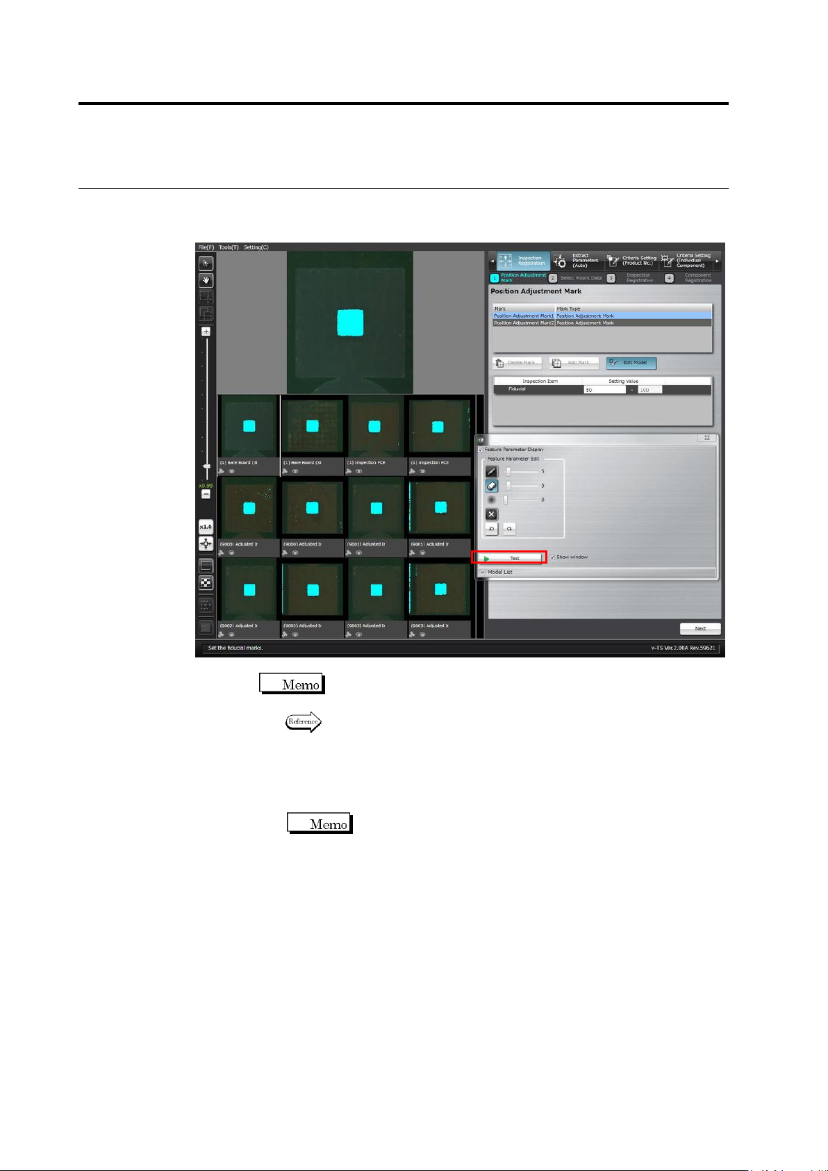
5.
The Model Editing screen is displayed.
Edit the color table to enable the detection of the adjustment marks.
Click [Test] to display the detection result in a blue window.
Position adjustment marks of other inspection PCBs or bare boards
are also displayed.
Refer to "Model Editing Screen Operation" for the details on Model
Editing screen operation.
6.
Click [Next] at the bottom right of the screen to proceed to the
Select Mount Data screen.
The [Next] button will be enabled after conducting a test.
2.4 Registering for Inspection
2-41
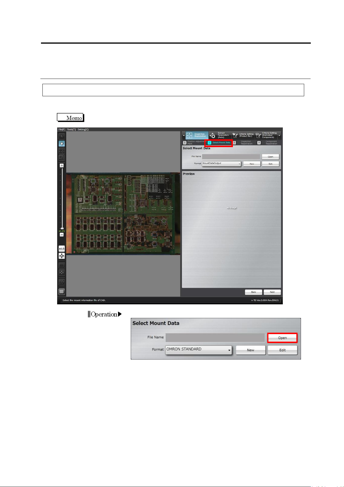
2.4.2 Selecting Mount Data
Obtain the information such as the component coordinates, component number and circuit
number from the selected mount data.
Loading of mount data is not required for a new inspection program. Skip this procedure and
click [Next] to proceed to "2.4.4 Inspection Registration".
1.
Click [Open] in the Select Mount Data section.
Operation
Chapter 2 Inspection Programming
2-42
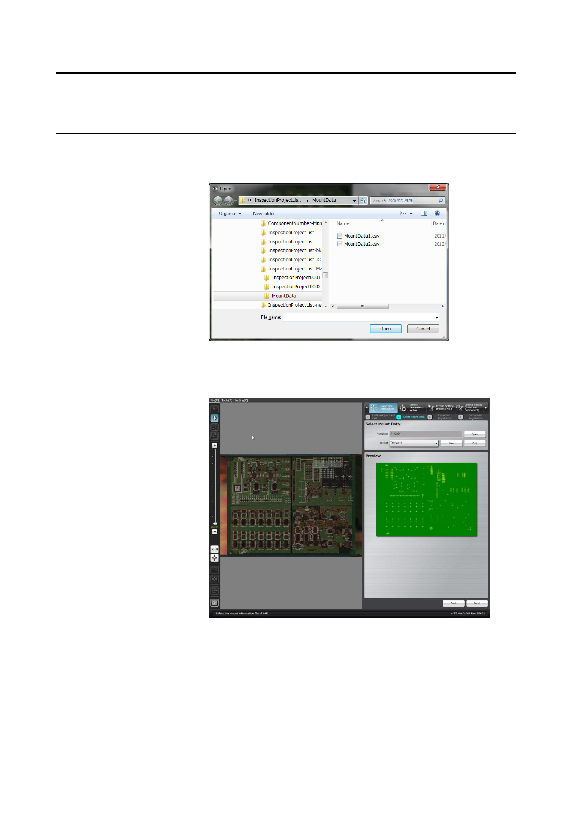
2.
The file selection dialog appears.
Specify the mount data file and click [Open].
Files with any extension can be read because there is no limitation
of extension.
3.
Select the format to display the data.
A map showing the positions of components is displayed in the
preview area when an appropriate format is selected for the mount
data.
If no corresponding format is available, click [New] or [Edit] to create
the format.