Omron V-TS Teaching Manual.pdf.pdf - 第125页
Chapter 2 Inspecti on Programm ing 2- 98 8. Click the button. T he result of the ba d mark , measured values, a nd judgm ent are displayed. The display of the inspecti on result of PCB tests is switc hed depending on whe…
Chapter 2 Inspection Programming
2-98
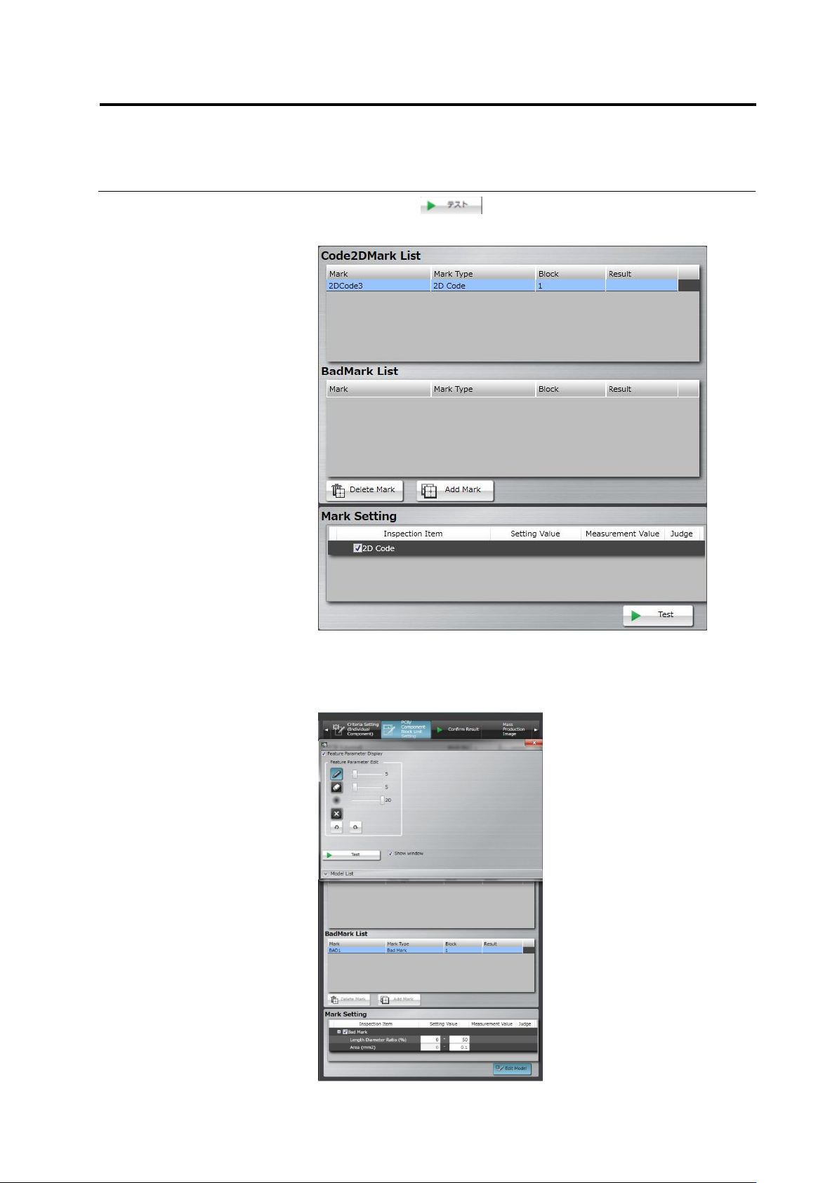
8.
Click the button. The result of the bad mark,
measured values, and judgment are displayed.
The display of the inspection result of PCB tests is switched
depending on whether a bad mark is detected or not.
- If detected: The inspection result of all the circuits of the
component block units to which the bad mark belongs is not
displayed.
- If not detected: The inspection result of the circuits is
displayed.
2.8 PCB Testing/Result Check
2-99
2.8 PCB Testing/Result Check
Test a created inspection program using PCBs to check the relevance of the inspection windows
and criteria. For PCB test, you can select either a PCB image captured upon creation of the
inspection program or an adjustment image under the adjustment mode. The modification of the
inspection program is required if inspection false calls are output.
2.8.1 Testing Using PCBs
Use a created inspection program to test a multiple number of PCBs.
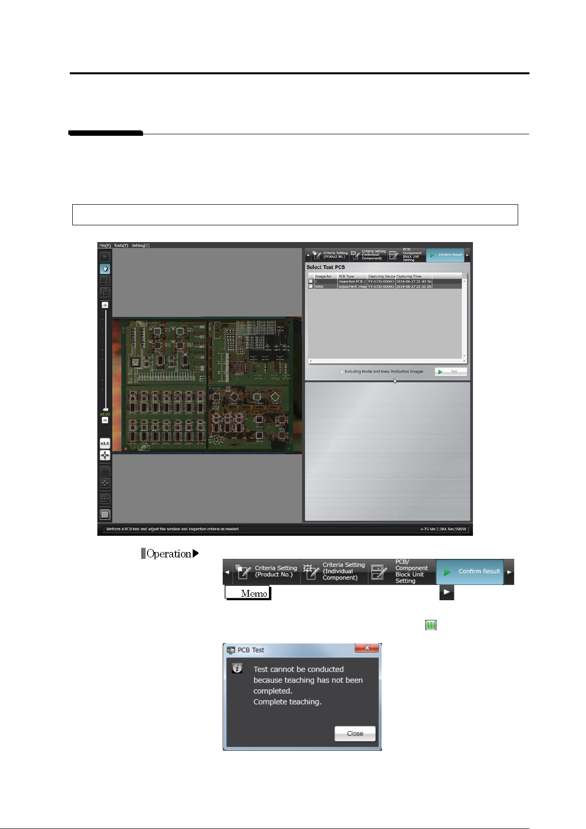
1.
Select the [Confirm Result] tab.
If the [Confirm Result] tab is hidden, click at the right to
display it.
When the all component number status is not , the dialog below
appears.
Click [Close] and exit teaching for all component numbers.
Operation