Omron V-TS Teaching Manual.pdf.pdf - 第164页
2.15 M odifying an Inspection Pr ogram 2- 137 The characteristic parameter values are common within the ranges specified below : Common with comp. No. Common with PCB Component color Yes Component extraction mask Yes Com…
Chapter 2 Inspection Programming
2-136
Window
Composition
Inspection Item
Feature Parameter
(Mask)
Window
Electrode Posture - Electrode
Side Bend
Component body top color + electrode color +
Electrode side bend color
Electrode Posture - Electrode
Height (Oblique)
Electrode color (Oblique) + position correction
color (Oblique)
Electrode Posture - Exposed
Electrode Toe (Oblique)
Electrode color (Oblique)
Electrode Posture - Electrode
Variation (Oblique)
Electrode color (Oblique)
Fillet Inspection
Fillet excluded color + component body top
color + electrode color
Exposed Basis Metal
Exposed land color
-
Foreign Material (Land)
Color of foreign material inside land
-
Exposed Basis Metal (Oblique)
Land color (for oblique),
position adjustment color (for oblique)
-
Abnormal Land
Abnormal land color, inspection are
specification
Abnormal Land (Oblique)
Land color (for oblique),
position adjustment color (for oblique)
Inspection
Region
Solder Ball
Solder ball color
Solder
ball/bridging
mask
Solder Bridge
Solder bridge color
Solder bridge color (lead shoulder) (for gull
wing only)
Foreign Material
PCB color (except resist, land, through-hole,
silk or other normally appearing colors)
Peripheral
foreign object
mask
Solder Ball (Oblique)
Solder ball/bridge color (for oblique),
position adjustment color (for oblique)
-
Solder Bridge (Oblique)
Solder ball/bridge color (for oblique),
position adjustment color (for oblique)
-
Refer to the Inspection Logic Manual for the details on the characteristic parameters of the
individual inspection items.
2.15 Modifying an Inspection Program
2-137
The characteristic parameter values are common within the ranges specified below:
Common
with comp.
No.
Common
with PCB
Component color
Yes
Component extraction mask
Yes
Component difference color
Yes
Polarity difference color
Yes
Component bottom side color
Yes
Missing component excluded color
Yes
Electrode color
Yes
Lifted electrode color
Yes
Electrode side bend color
Yes
Electrode color (oblique)
Yes
Land foreign object color
Yes
Abnormal land color
Yes
Abnormal land color (oblique)
Yes
Missing component mask
Selectable
Position adjustment color (oblique)
Selectable
Fillet excluded color
Selectable
Land exposed color
Selectable
Solder ball/bridging mask
Selectable
Peripheral foreign object mask
Selectable
Land color (oblique)
Yes
Solder color
Yes
Solder bridge color
Selectable
Solder bridge color (lead shoulder)
Selectable
Solder ball color
Selectable
PCB color
Yes
Solder ball/bridge color (oblique)
Yes
Position adjustment color
Yes
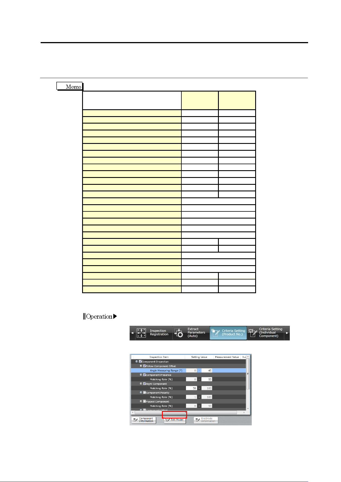
The following description explains the model editing procedure.
1.
Select the [Criteria Setting (Product No.)] or [Criteria Setting
(Individual Component)] tab.
2.
Select the inspection item to edit and click [Edit Model].
Operation
Chapter 2 Inspection Programming
2-138
Refer to "2.6.1 Criteria Setting (Product No.)" for the procedure up to
selecting the inspection item if [Criteria Setting (Product No.)] is
selected, and "2.6.2 Criteria Setting (Individual Component)" for the
same if [Criteria Setting (Individual Component)] is selected.
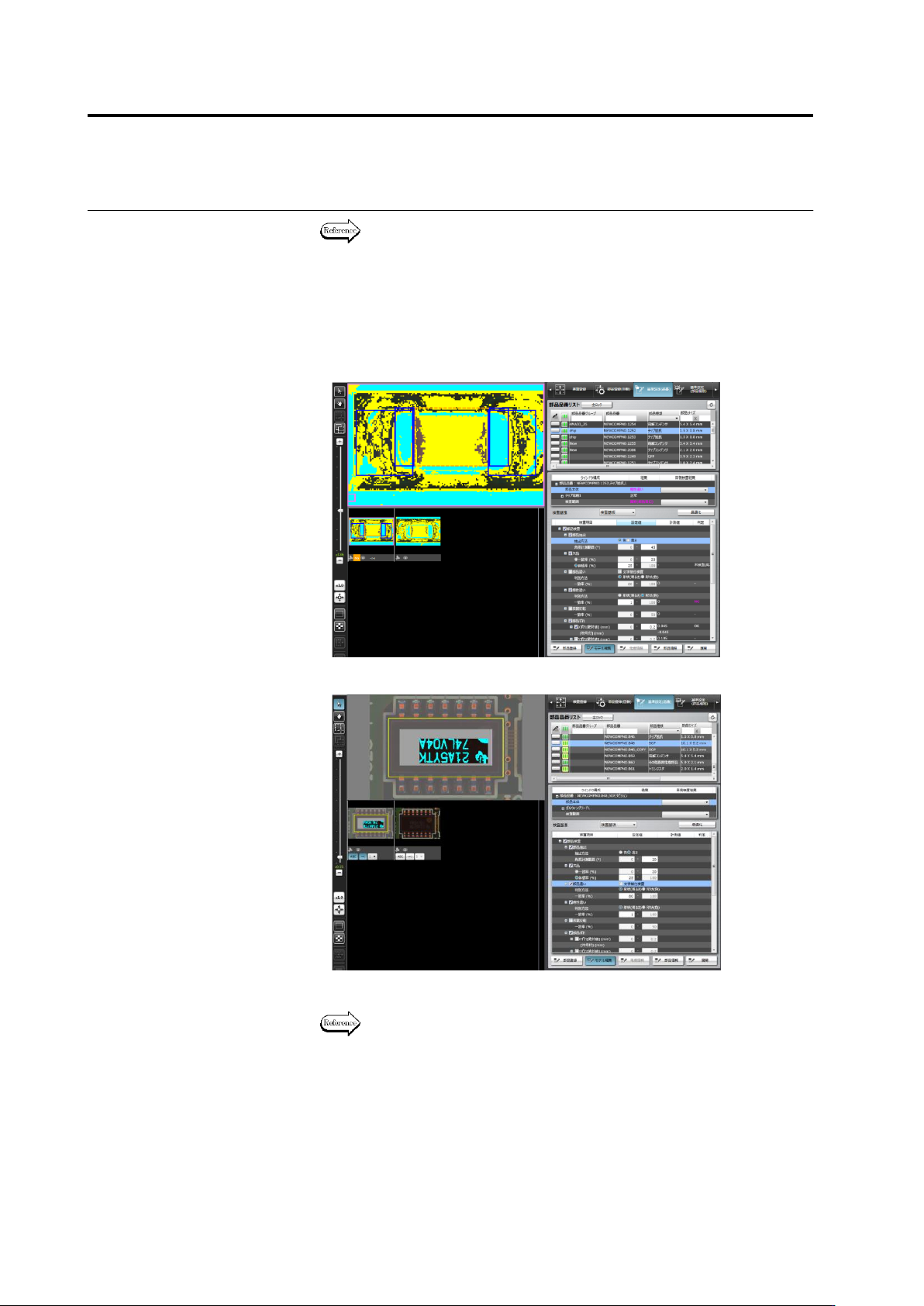
3.
A different model editing screen is displayed depending on the
characteristic parameter to edit.
・
Color Characteristic Parameters
・
Mask Model Characteristic Parameters
4.
Edit the characteristic parameters.
The operation method of the model editing screen is described on the
next page.
5.
To continue the editing of other characteristic parameters, click any
of the inspection items allowed for model editing.
The Model Editing screen closes if [Edit Model] is clicked.