Omron V-TS Teaching Manual.pdf.pdf - 第45页
Chapter 2 Inspection Programm ing 2- 18 Change Magnification Ratio <Magnif y/Reduce> The im age can be enlarged or reduced in th e following three wa ys: 1) Click (Magnif y) button or (Reduce) button in the Image…
2.1 Basics of Teaching
2-17
2.1.3 Image Display Area Operation
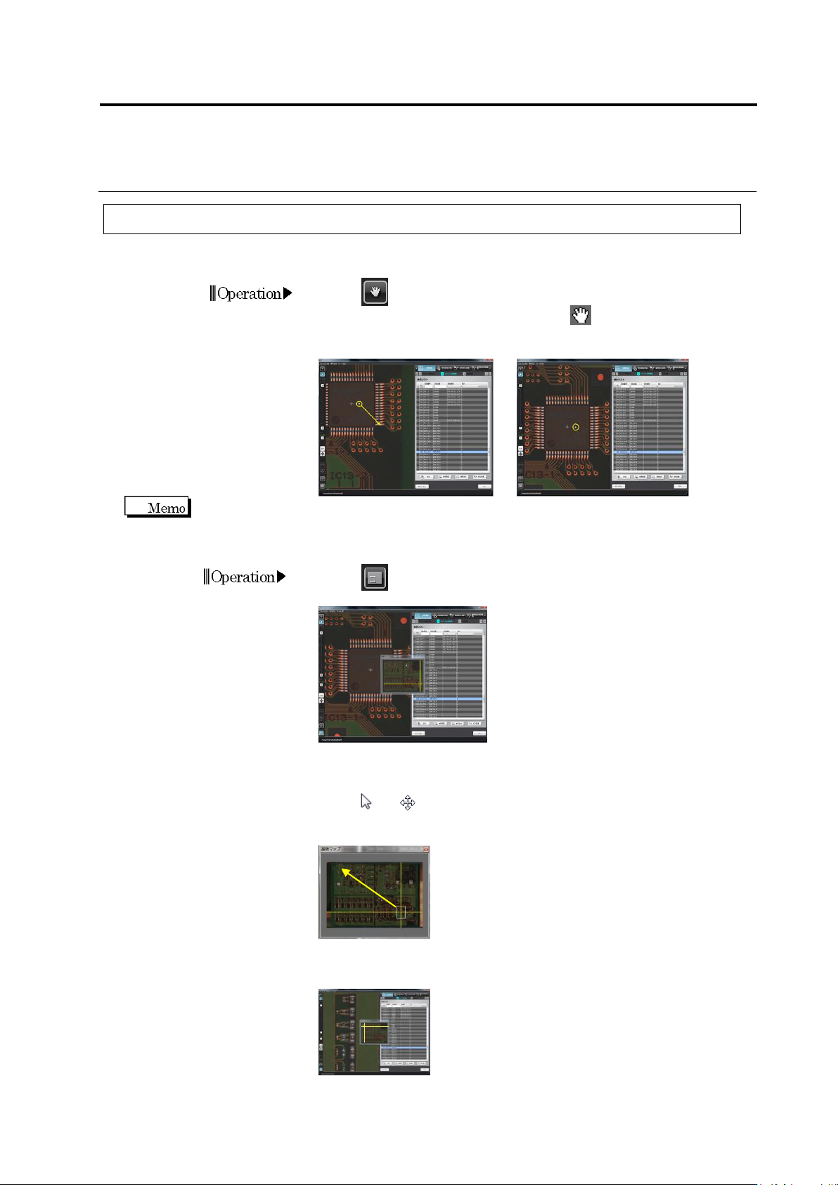
Move Field of Vision
<For Small Movement>
1.
Click (Move Field of Vision) button in the Image Operation
tool bar. The mouse cursor changes to .
2.
Drag and drop the PCB image to change the field of vision.
Drag and drop using the right mouse button, instead of using the image operation button, can also
move the field of vision.
<For Large Movement>
1.
Click (PCB Map) button in the Image Operation tool bar to
display the PCB map.
2.
Locate the mouse cursor on the field of vision window in the PCB
map (intersection of the yellow lines). The mouse cursor changes
from to .
3.
Drag the field of vision window in the PCB map.
4.
Drop the window at a desired location in the PCB map to position
the field of vision.
Operation
Chapter 2 Inspection Programming
2-18
Change Magnification Ratio
<Magnify/Reduce>
The image can be enlarged or reduced in the following three ways:
1) Click (Magnify) button or (Reduce) button in the Image Operation tool bar.
2) Move the slide bar up or down in the Image Operation tool bar.
Move it upward to magnify, and downward to reduce.
3) Position the mouse cursor on the image display area and rotate the mouse wheel.
Rotate it upward to magnify, and downward to reduce.
The magnification ratio changes by one step increment as shown below:
Maximum reduction ratio
x0.01 -> … ->
…
-> x0.25 -> x0.50 ->
×
1.00 -> x2.00 ->
…
-> x4.00
<Original Size Display>
1.
Click (Original Size) button in the Image Operation tool bar.
The software displays one pixel of the camera image in the same
size (100%) as one pixel of the image display area.
<Entire PCB Display>
1.
Click (Entire View) button in the Image Operation tool bar.
The entire PCB view is displayed.
Operation
Operation
2.1 Basics of Teaching
2-19
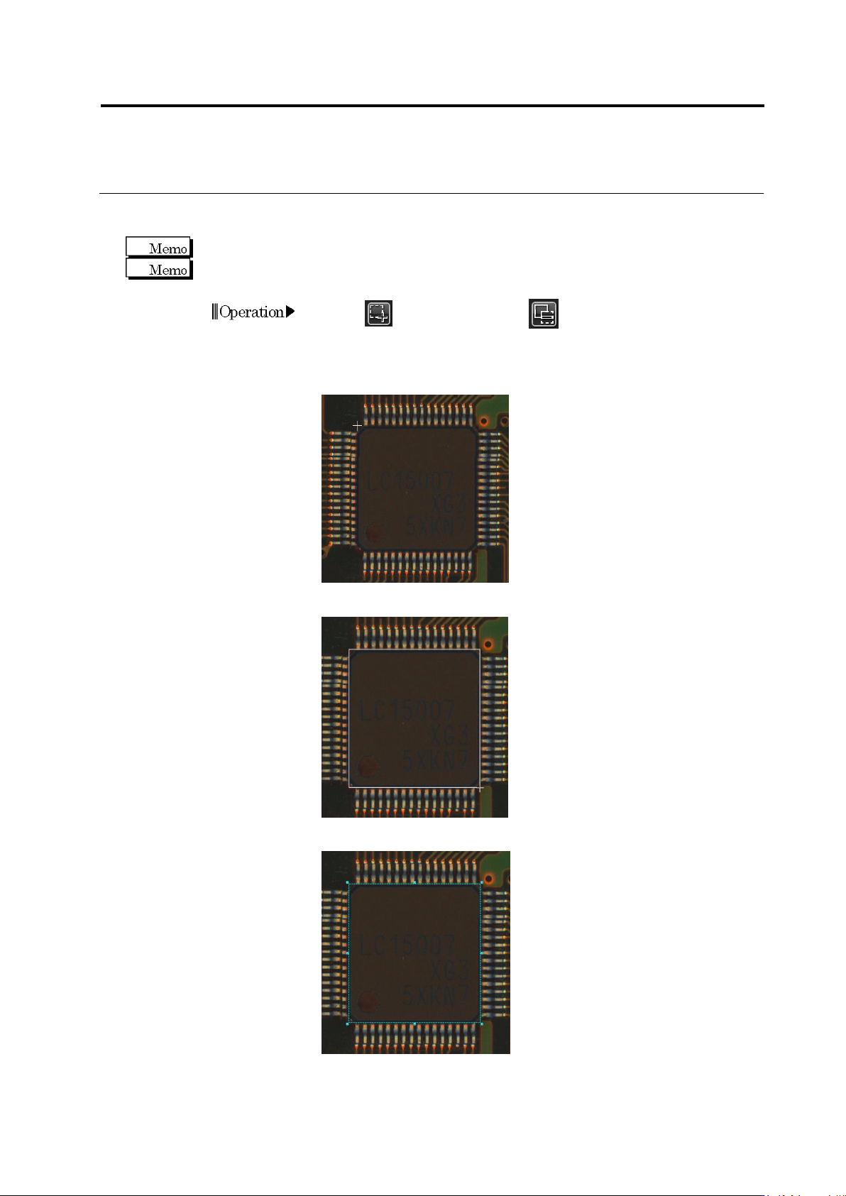
Create Window
When creating a window, set the display magnification to 1.0 times or higher.
A window in a size smaller than 0.1 mm × 0.1 mm cannot be created.
1.
Click (Create Window) or (Create Mask Window) button
in the Image Operation tool bar.
2.
Move the mouse cursor at the top left corner of the window to
create, surrounding the relevant location e.g. component or land.
3.
Drag the cursor from the left top point diagonally to the right bottom.
4.
Drop the cursor. The window is formed.
Operation