Omron V-TS Teaching Manual.pdf.pdf - 第76页
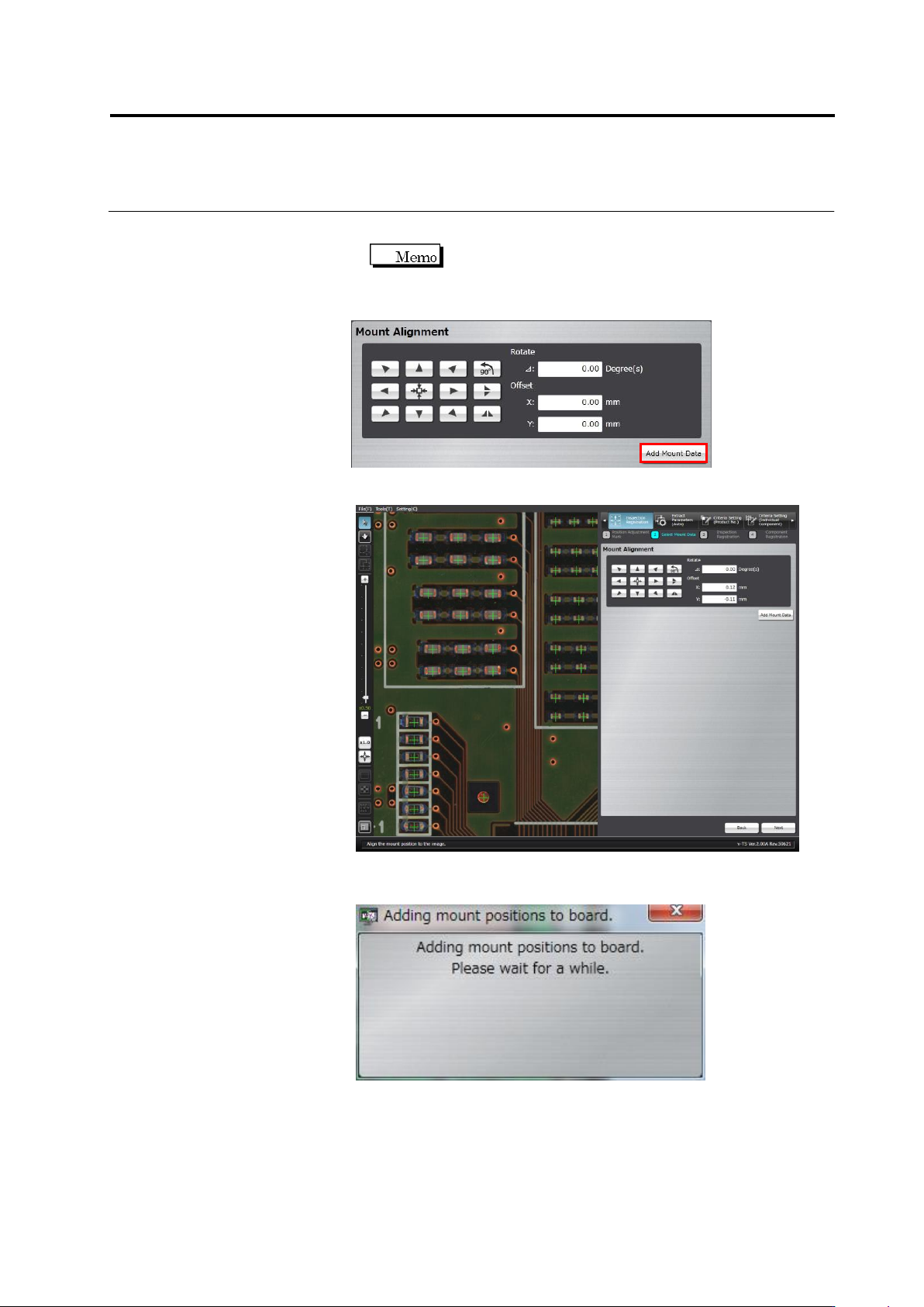
2.4 Registeri ng f or Insp ection 2- 49 Up to two decimal places can be entered for the rotation angle and offset values. 2. Click [Add Mount D ata] to add m ore mount data and repeat Ste p 1. 3. Click [Next]. The mount …
Chapter 2 Inspection Programming
2-48
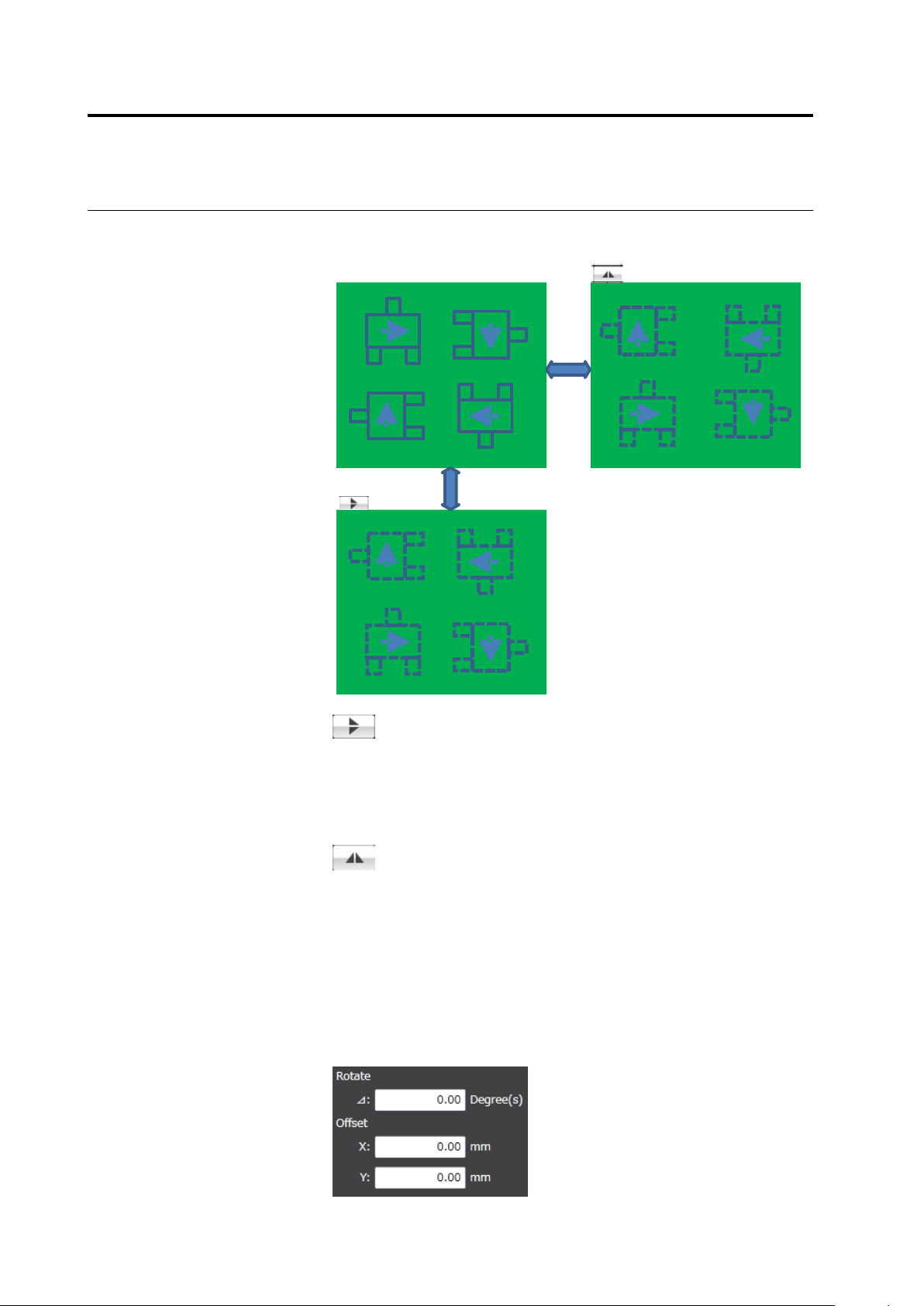
The upper/lower reverse button and the right/left reverse button
operate as follows:
Right/left reverse
Upper/lower
reverse
Upper/lower reverse
The component coordinates are relocated vertically by line
symmetry. The angle of each component is not converted.
It is assumed that the mount data are kept with the
components on the back of the PCB permeating the PCB
and the angles of them are correct.
Right/left reverse
The component coordinates are relocated horizontally by
line symmetry. The angle of each component is rotated at
180 degrees.
It is assumed that the mount data are kep with the
components on the back of the PCB permeating the PCB
and the angles of them are correct.
◆
Adjustment by Inputting Values
The rotation angle and offset values obtained by the mouse or
button operation are shown in the screen. Edit the angle and X and
Y coordinate values directly for fine tuning.
2.4 Registering for Inspection
2-49
Up to two decimal places can be entered for the rotation
angle and offset values.
2.
Click [Add Mount Data] to add more mount data and repeat Step 1.
3.
Click [Next].
The mount position addition processing dialog appears. After
processing, the screen returns to the inspection registration screen.
Chapter 2 Inspection Programming
2-50
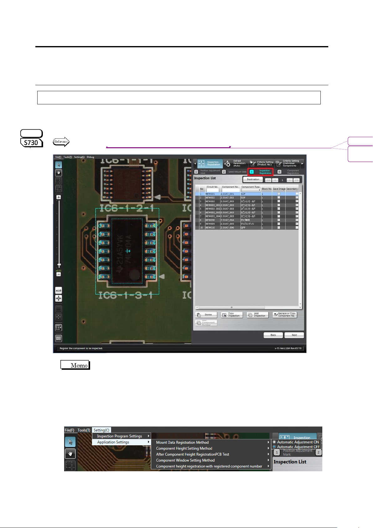
2.4.4 Inspection Registration
Register components to inspect based on the component information in the loaded mount data.
Also the components whose images are saved while inspection is performed can be selected.
Specify the inspection direction for the component numbers for oblique inspection, individually for
each component.
Refer to "2.9.3 Specifying Oblique Inspection Component and Direction" for the procedure to specify the
oblique inspection direction.
The software normally detects misalignment of the component position
automatically, and adjust it automatically from the position of the mount data.
When registering the component position in the position of the mound data to inspect misalignment
based on the mount data, turn OFF automatic adjustment by the following steps.
(The ON/OFF setting of automatic adjustment is saved in the v-TS terminal. This setting is
used by any inspection program.)
1. Select [Setting] - [Application Settings] - [Mount Data Registration Method], and check
[Automatic Adjustment OFF].
2. Execute inspection registration using the operation procedure below.
S720A
書式変更: フォント : (英) Arial, 9 pt
削除: Specifying Oblique Inspection
Component and Direction