Omron V-TS Teaching Manual.pdf.pdf - 第131页
Chapter 2 Insp ection Progr amming 2- 104 ・ Component Image Displays a list of the inspec tion fault com ponent thum bnail images rel evant to the com ponent number selected in the PCB Test Result list. Also shows a m ag…
2.8 PCB Testing/Result Check
2-103
2.8.2 Interpreting PCB Test Result
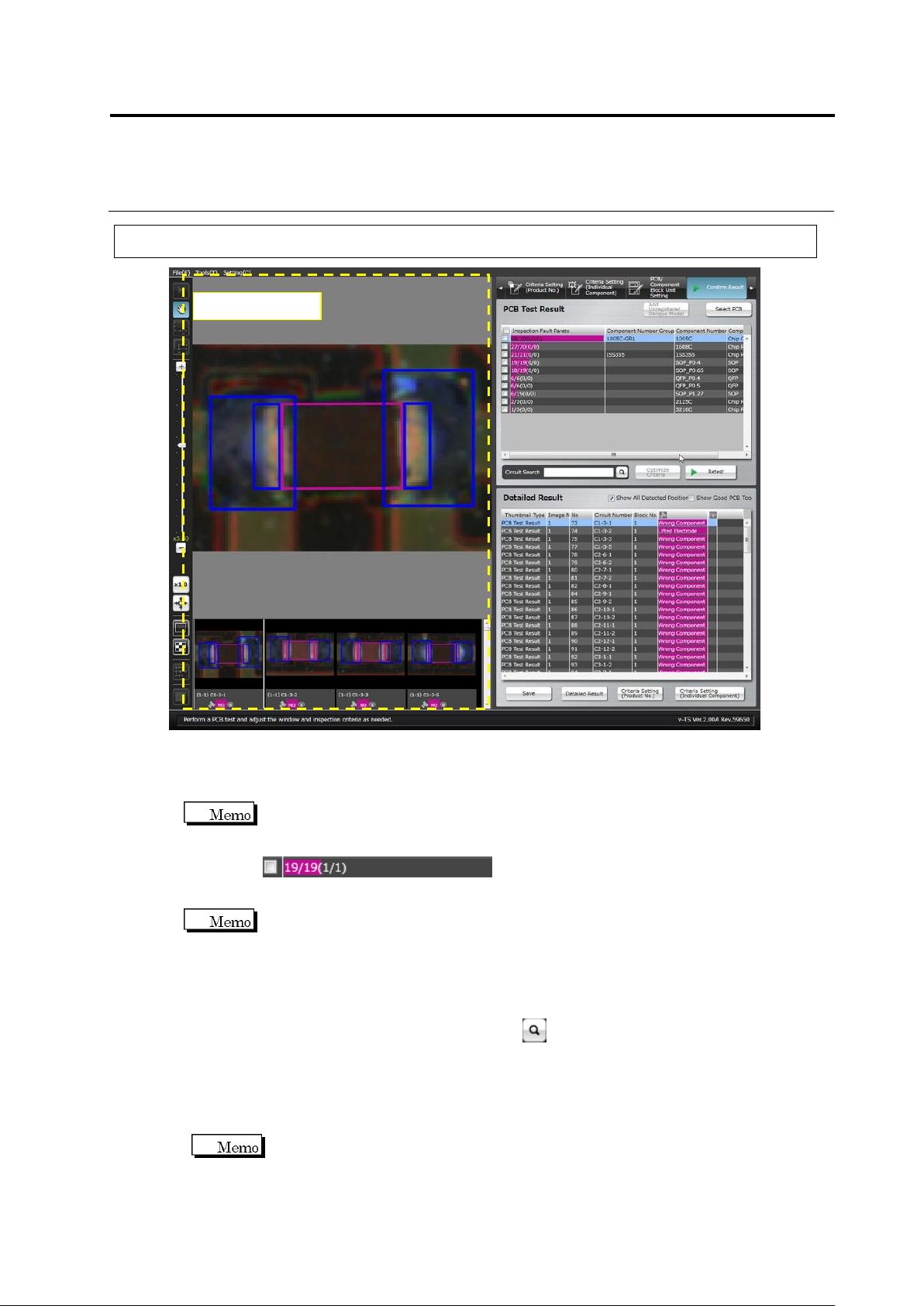
・ PCB Test Result
Shows the PCB test result as the number of inspection faults in a Pareto chart by the unit of
component number.
The numbers displayed on the inspection fault palate indicate the resultant numbers of
component inspection.
NG components / All components (detected faults / actual faults)
Detected faults: The number of faults which were detected as faulty by the inspection
Actual faults: The number of visually registered actual faults
Reducing undetected fault means reducing the difference between the detected faults and
actual faults.
・ Detailed Result
Displays a list of the inspection fault components and judgment results pertaining to the
component number selected in the PCB Test Result list.
Enter a circuit name in [Circuit Search] and click button, then select a line with the same
name from the detailed result list.
Click the [Show Good PCB Too] checkbox ON also to display components judged good.
Selecting the [Show All Detected Position] checkbox displays the Component Body Window,
electrode windows and land windows extracted in inspection. Deselecting the checkbox
does not display the windows.
If multiple inspection items are judged faulty for a single component, the result is
displayed in the order from smaller fault codes.
Component Image
Chapter 2 Inspection Programming
2-104
・ Component Image
Displays a list of the inspection fault component thumbnail images relevant to the component
number selected in the PCB Test Result list. Also shows a magnified image of the
component selected in the Detailed Result list or the component thumbnail image list.
The windows where a fault is detected are displayed in a pink frame.
The components in the thumbnail images are displayed at 0 degrees angle.
The (image No. – component block unit No.) circuit number, test result (OK/NG),
visual check result with v-CA (OK/NG/None) are displayed below the individual
component thumbnail images.
Oblique images are not displayed, if the test is performed on a PCB used for oblique
image capturing.
S720A
2.8 PCB Testing/Result Check
2-105
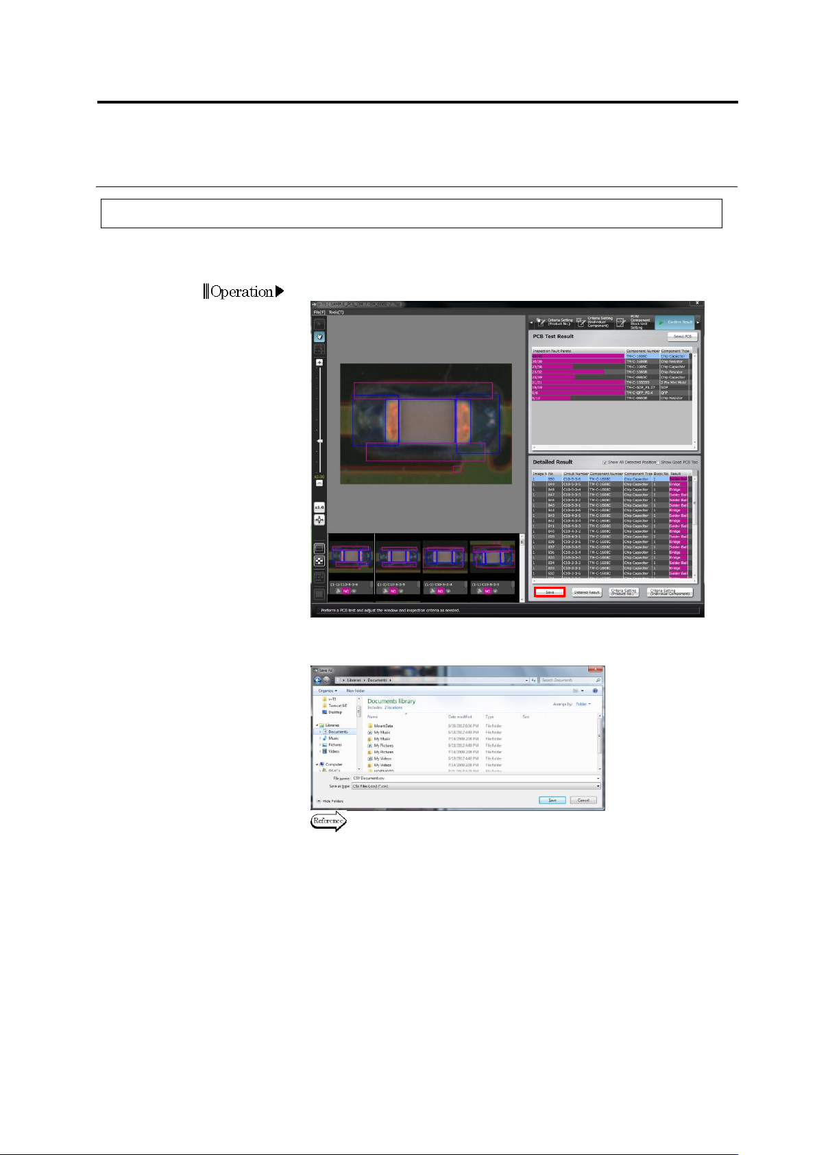
2.8.3 Saving Inspection Result
This section explains the procedure to save the PCB test result in the CSV format.
It is used for managing the PCB test result, etc.
1.
Click [Save].
2.
The file save dialog appears. Select the save destination, specify
the file name and click [Save].
Refer to the next page for the details of output formats.
Operation