Omron V-TS Teaching Manual.pdf.pdf - 第139页
Chapter 2 Insp ection Progr amming 2- 112 5. Select a window you wish to edit. 6. Specify ON of OFF or the oblique inspectio n chec kbox and edit criteria values. Com ponent numbers cannot be edited if their oblique imag…
2.9 Setting Oblique Inspection
2-111
2.9.2 Setting Criteria for Oblique Inspection Items
This section describes the procedure to specify the criteria for oblique inspection.
1.
After capturing oblique image with the system, select the inspection
program in the Select PCB screen on v-TS, and click [Edit].
2.
Select an adjustment image with oblique to perform a PCB test.
3.
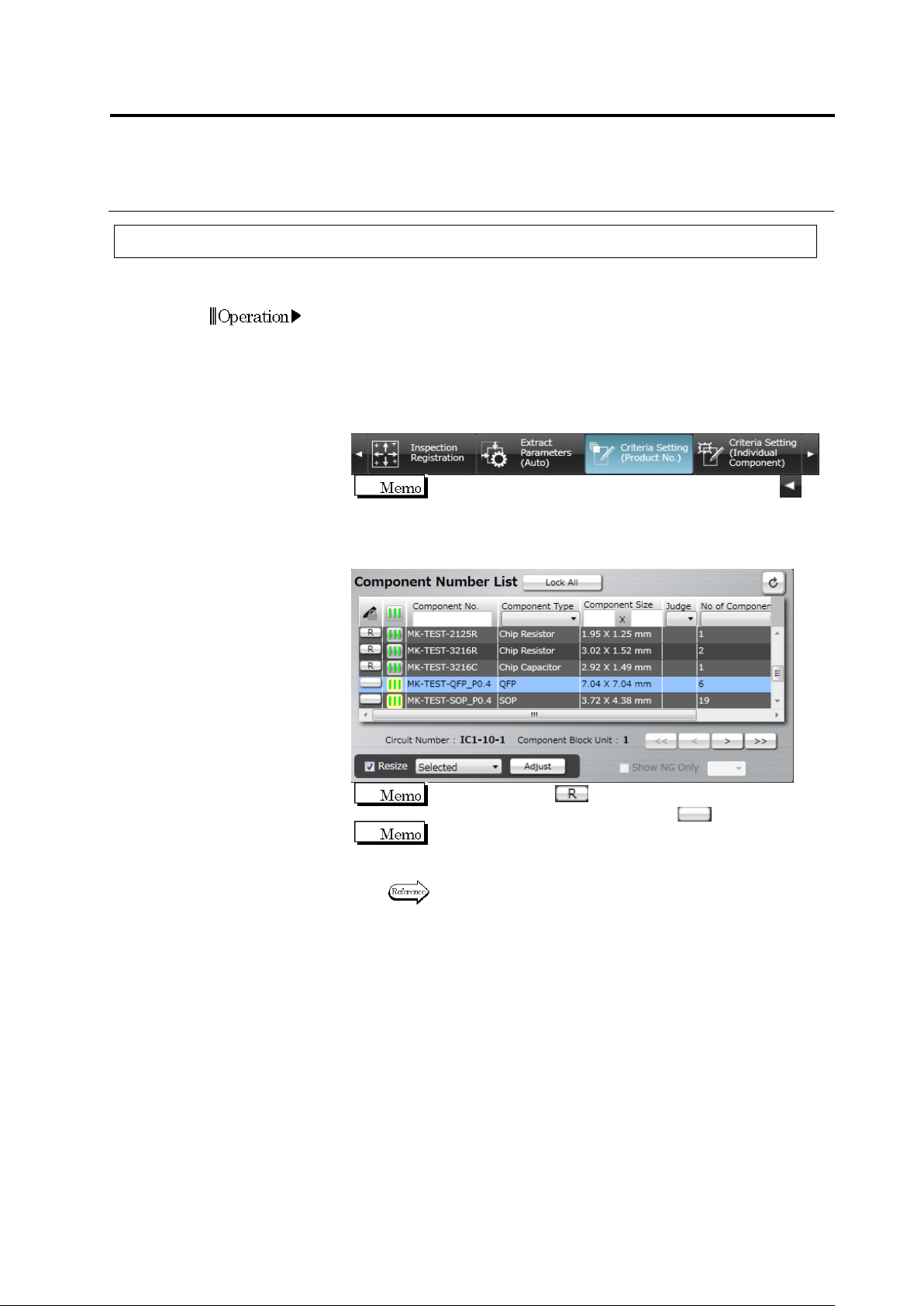
Select the [Criteria Setting (Product No.)] tab to display the Criteria
Setting screen.
If the [Criteria Setting (Product No.)] tab is hidden, click at
the left to display it.
4.
Select the component number for oblique inspection in the
Component Number List.
When the status is (locked), click it to change the
component number state to not locked .
The progress signal is shown in the light yellow background in
the Component Number List for oblique inspection target
component numbers.
Refer to (5) Information Display Area of "2.1.2 Configuration of
the Editing Screen" for details on the progress signals.
Chapter 2 Inspection Programming
2-112
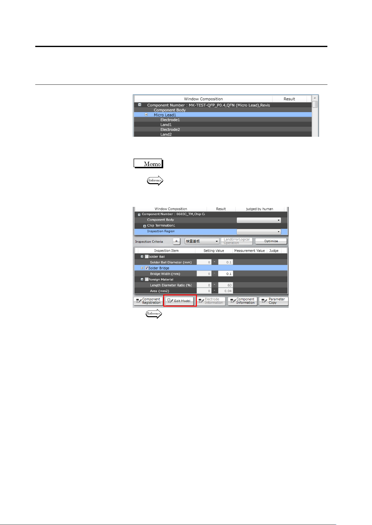
5.
Select a window you wish to edit.
6.
Specify ON of OFF or the oblique inspection checkbox and edit
criteria values.
Component numbers cannot be edited if their oblique image is
not captured yet.
Refer to the Inspection Logic Manual for the details on the
inspection items.
7.
To edit characteristic parameters, click [Edit Model].
Refer to "2.15.3 Editing a Model" for the model editing
procedure.
2.9 Setting Oblique Inspection
2-113
2.9.3 Specifying Oblique Inspection Component and Direction
This section explains the procedure to specify if oblique inspection is performed or not, as well as
the procedure to set the direction of oblique inspection (if it is performed).
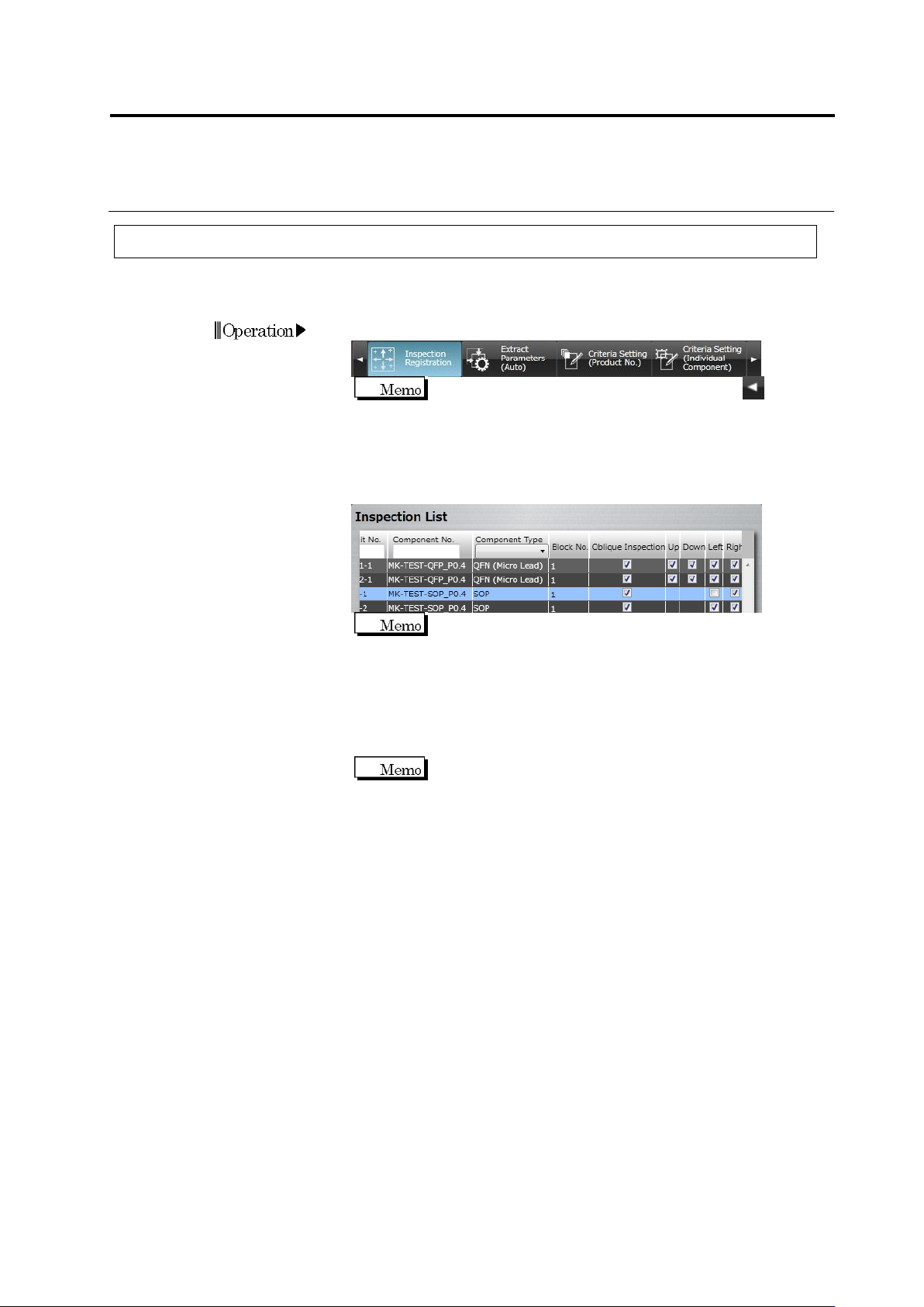
1.
Select the [Inspection Registration] tab.
If the [Inspection Registration] tab is hidden, click at the
left to display it.
2.
The display switches to the Inspection Registration screen.
Checkboxes are displayed at the Oblique Inspection column, and
the Top, Bottom, Left and Right columns in the direction of the
electrode window.
Slanted components (the component angle is other than 0°,
90°, 180°, or 270°) cannot be targets for oblique inspection
and therefore, checkboxes are not displayed for them.
Turn OFF the oblique inspection checkbox for components, if
oblique inspection is not performed for them. Turn OFF the
checkbox of specific directions, in which oblique inspection is not
performed, if there are any.
Turn OFF the direction where oblique inspection is obstructed
due to a large adjacent component.