Omron V-TS Teaching Manual.pdf.pdf - 第339页
Appendix 10 . Insp ection Criteria Settin g a- 62 2) If overlooking or false ca ll is detected in th e “ W etting Inspection S tatus ” are a, press the [Select Wetting Inspection Item ” button. Then, the logical expres s…
Appendix 10. Inspection Criteria Setting
a-61
Appendix 10. Inspection Criteria Setting
1. Logical expression and inspection criteria setting
(1) Select the Criteria Setting (Component Number) tab.
(2) If there is an actual fault, register the visual inspection result on the component body, land, and
terminal items.
(3) Press the [Optimize] button to display the inspection criteria setting screen.
(4) Operations on the inspection criteria setting screen
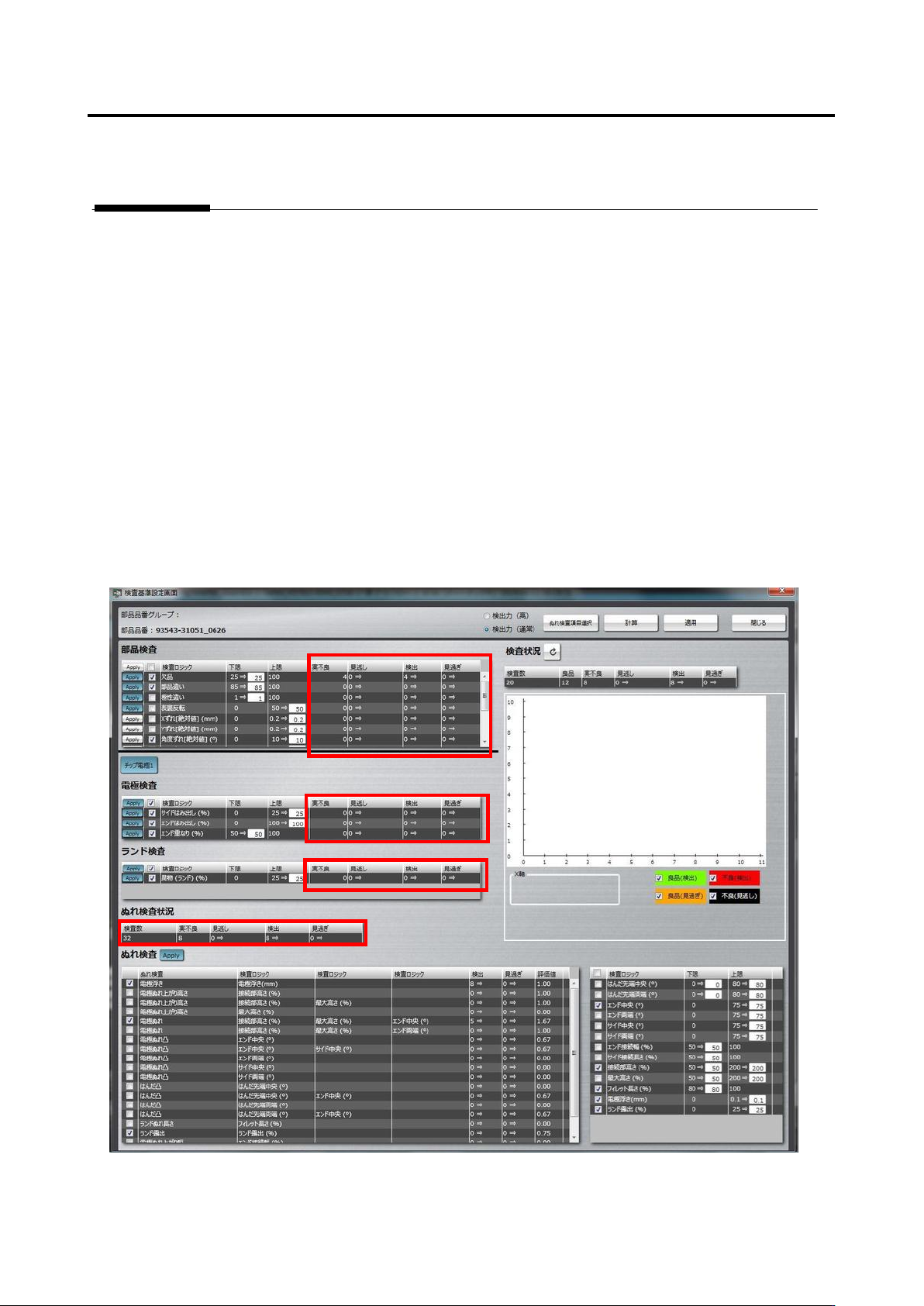
1) On the left portion of the screen, confirm that the numbers of overlooking and false call are zero in
the “Component Inspection,” “Electrode Inspection,” “Land Inspection,” and “Wetting Inspection
Status” areas. If they are zero on both the columns, adjustment of this product number is
completed.
Appendix 10. Inspection Criteria Setting
a-62
2) If overlooking or false call is detected in the “Wetting Inspection Status” area, press the [Select
Wetting Inspection Item” button.
Then, the logical expressions on the left side of “Wetting Inspection” are switched between
effective and not effective.
3) Press the [Calculate] button.
4) If the number of overlooking or false call varies, the number background turns green. So, confirm
how the background has changed.
4)-1 If the number of overlooking or false call is zero, press [Apply] and [Close] to close the
screen.
4)-2 If there is an overlooking or false call, confirm the extraction status, component information,
and color parameters of the logic, and correct them if not appropriate.
4)-3 If OK and NG products are separated and difference from the set reference value is very
small on the inspection screen, make the setting criteria manually.
4)-4 If it is no problem even when an inspection item is not specified, deselect the inspection item.
4)-5 If false call or overlooking still remains even after performing step 4)-1 to 4)-4 above, use the
functions of land error.
For details of land error, refer to P5-17 section 5.10 “Land Error” of the inspection logic
manual.
Appendix 11 PCB Test Result Output Format
a-63
Appendix 11. PCB Test Result Output Format
The PCB test result output function is used when all the measured values of the target component
are output to analyze the inspection result and those measured values or when saving all the
measured values of the PCB test result.
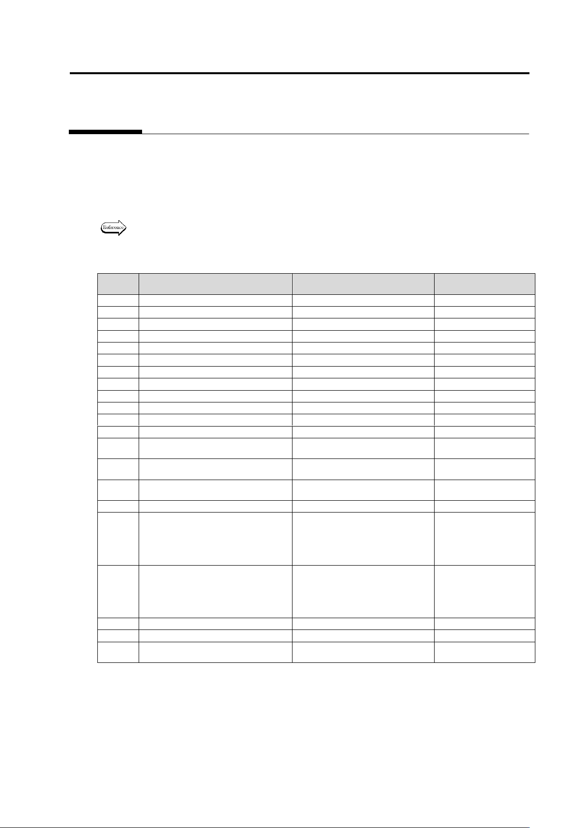
The inspection result of the PCB test is output in the following format on a component basis or on a
pin basis.
For the method to output the PCB test result, refer to Section 2.8.3 “Saving
Inspection Result.”
Items that inspection result is outputted for each component have O, and the other ones X.
Column
Item
Description
Output of result for
each component
1
BoardId
PCB ID
○
2
InspectionResultNo
No.
○
3
CircuitId
Circuit ID
○
4
ComponentNumberGroupName
Group name of component
×
5
ComponentNumberGroupId
Group ID of component
×
6
ComponentNumberName
Name of component No.
○
7
ComponentType
Type of component
○
8
ComponentResult
Inspection result of component
○
9
ComponentBlockUnitName
Component block unit name
○
10
ElectrodeGroupId
Electrode group ID
×
11
ElectrodeType
Electrode type
×
12
PinNumber
Pin No. of electrode
×
13
ComponentWidthOrElectrodeLength
Component window’s width /
Electrode length [um]
○
14
ComponentHeightOrElectrodeWidth
Component window’s height /
Electrode width [um]
○
15
AngleFromComponent
Angle viewed from component
[deg]
○
16
AngleFromBoard
Angle viewed from PCB [deg]
○
17
DeltaXorLength
ΔX/Length[um]. This means shift
in the X-direction on the PCB in
the case of component window,
and variation of length in the case
of electrode window, respectively.
○
18
DeltaYorSide
ΔY/Side[um]. This means shift in
the Y-direction on the PCB in the
case of component window, and
side shift in the case of electrode
window, respectively.
○
19
DeltaAngleDegree
ΔAngle[deg]
○
20
VisualResultType
Result of visual inspection
○
21
ElectrodeLandResult
Inspection result of electrode and
land
○
For the 22th column and after, the reference setting, measured value (Value), judgment result
(Result), upper limit (UpperLimit), lower limit (LowerLimit), and judgment method
(LogicMethodType) of each inspection item are output.
The output of Result is 0, 1, and a fault code, which mean OK judgment, not applicable to the
inspection, and NG, respectively.
The output item of the setting and description of it are shown on and after the following page.