Omron V-TS Teaching Manual.pdf.pdf - 第300页
Appendix 7. Positio n Correction/Extractio n a- 23 5. Component ext raction A com ponent is ex tracted in the i nspection range window , the positions of the com ponent body window and electrode windo w are correc ted an…
Appendix 7. Position Correction/Extraction
a-22
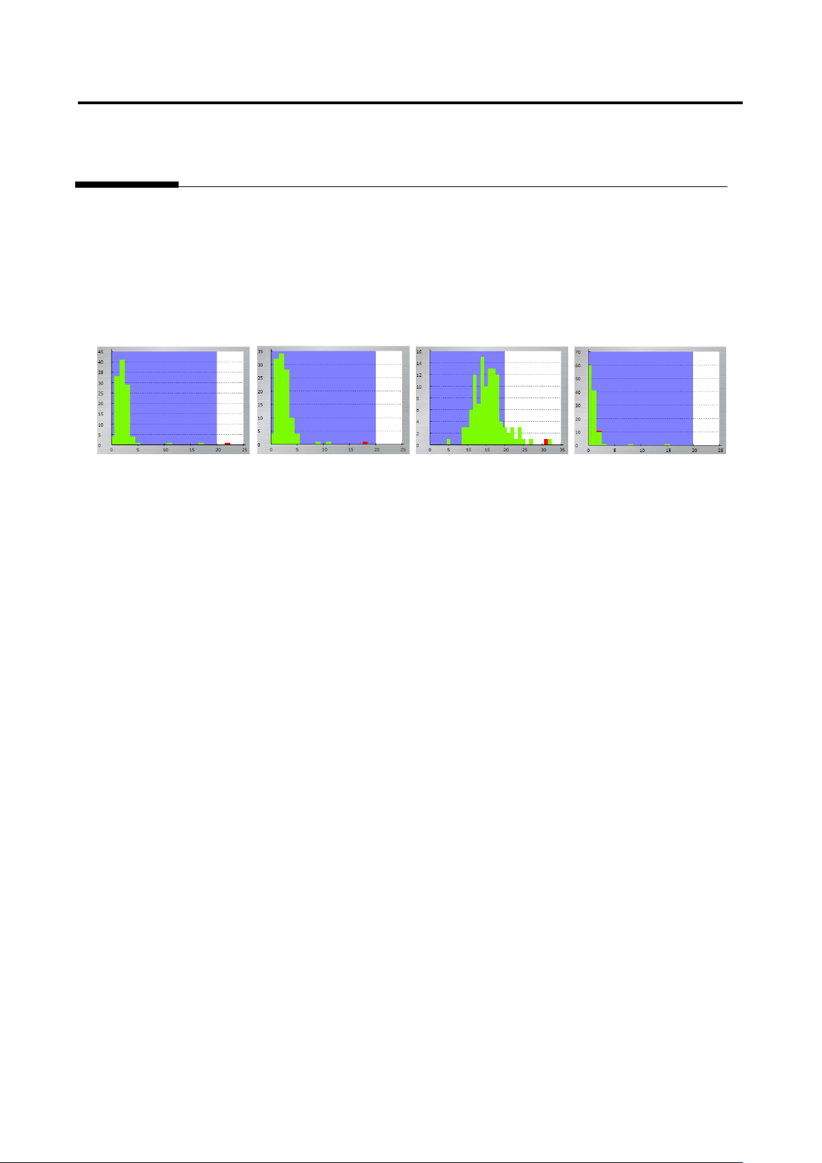
In the two figures on the left, the values are within the inspection criteria, and in the two figures on the
right, the values are not within the inspection criteria. “The good and fault can be separated” means all
the good components are within the inspection criteria, and faulty components are not. Even if faulty
components are inside the inspection criteria, there is no problem if the interval between the measured
value of the good component closest to the fault and the measured value of the fault is as follows:
Unit of %: 5%
Unit of angle: 1
Unit of mm: 0.05 mm
Appendix 7. Position Correction/Extraction
a-23
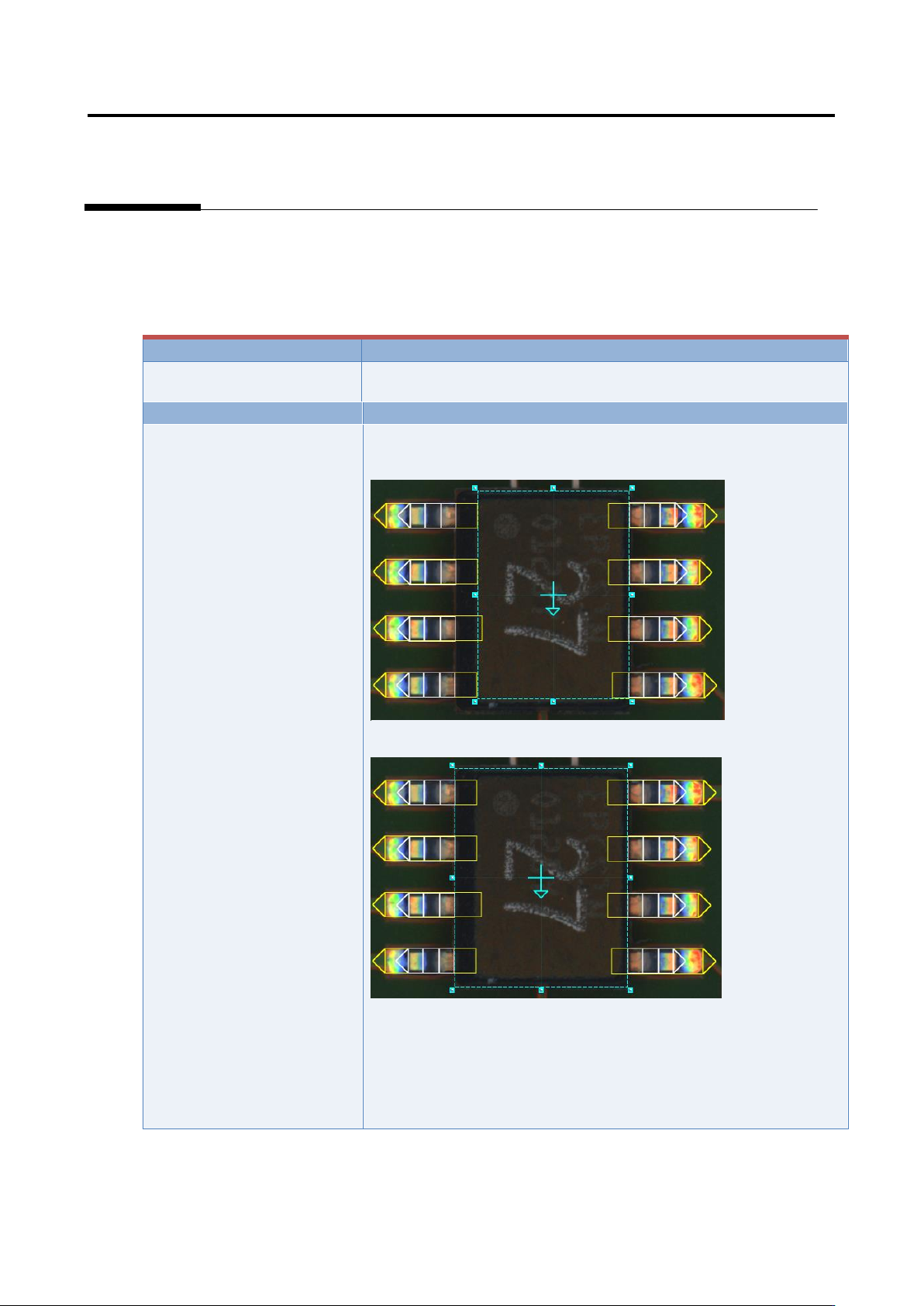
5. Component extraction
A component is extracted in the inspection range window, the positions of the component body window
and electrode window are corrected and specified as the reference positions for the component body
inspection and electrode inspection.
Inspection result
Component image (PCB test)
Cause
Confirmation and repair method
The component body window
and electrode window are not
sized appropriately.
1) Move to the “Inspection Registration” tab.
2) Confirm that the component body window has an appropriate
size.
3) If not appropriate, change the size/position of the component
body window, and click the [Next] button.
4) Click the [Next] button.
5) Click the [Next] button.
6) Confirm that the electrode window has a size consistent with
the image.
7) If not consistent, change the electrode window’s size/position.
Appendix 7. Position Correction/Extraction
a-24
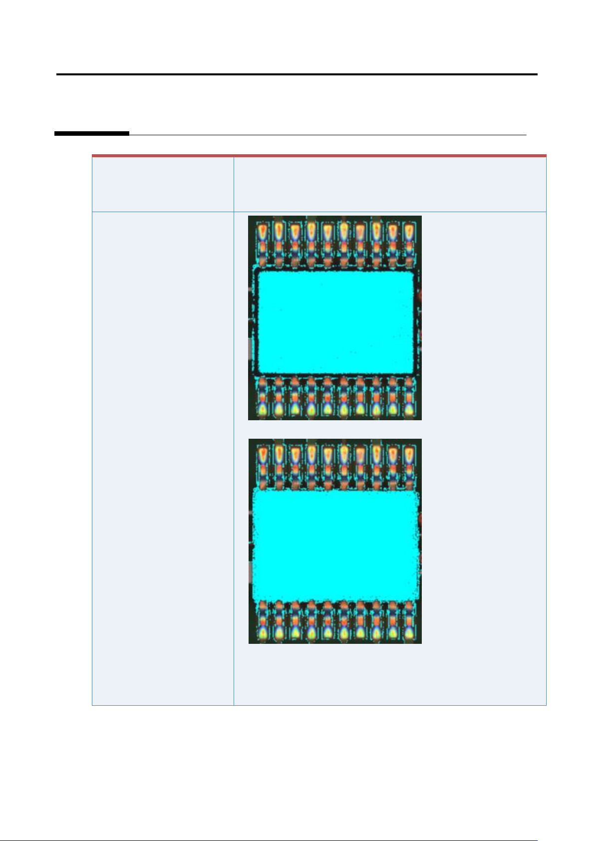
If the component has a tilted
side
Characteristic parameters
are not set appropriately.
(The component body color
and electrode color are not
being set sufficiently.)
1) Set the parameters if not set.
2) Select “Inspection Criteria” - “Extract Electrode Tip,” and click
the [Model Editing] button.
3) Confirm if the electrode color is being set.