Omron V-TS Teaching Manual.pdf.pdf - 第137页
Chapter 2 Insp ection Progr amming 2- 110 3. The Com ponent Registration screen is displ ayed. Select the component num ber for oblique inspection in the Component Number List, and sel ect "Yes" in the ob lique…
2.9 Setting Oblique Inspection
2-109
2.9 Setting Oblique Inspection
Oblique inspection requires the settings for oblique inspection target component numbers,
oblique image capturing, inspection criteria and direction. This chapter describes the procedures
to make individual settings and test PCBs for oblique inspection.
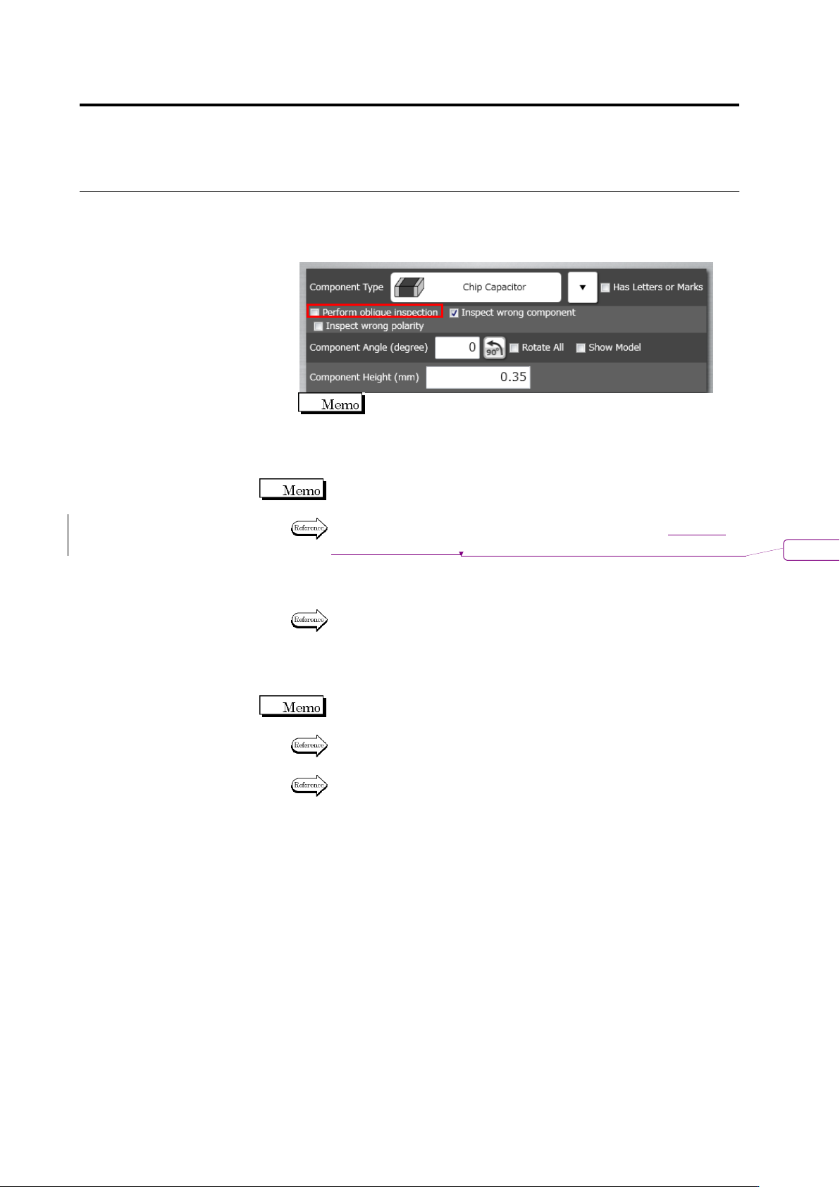
You cannot specify oblique inspection for BGA/CSP, other bottom electrode
component, and insertion component.
2.9.1 Setting Oblique Inspection Target Component Number
This section explains the procedure to specify an existing component number to the target of
oblique inspection.
Refer to "2.4.5.1 Component Setting" for the procedure to specify a new component number to the
target.
1.
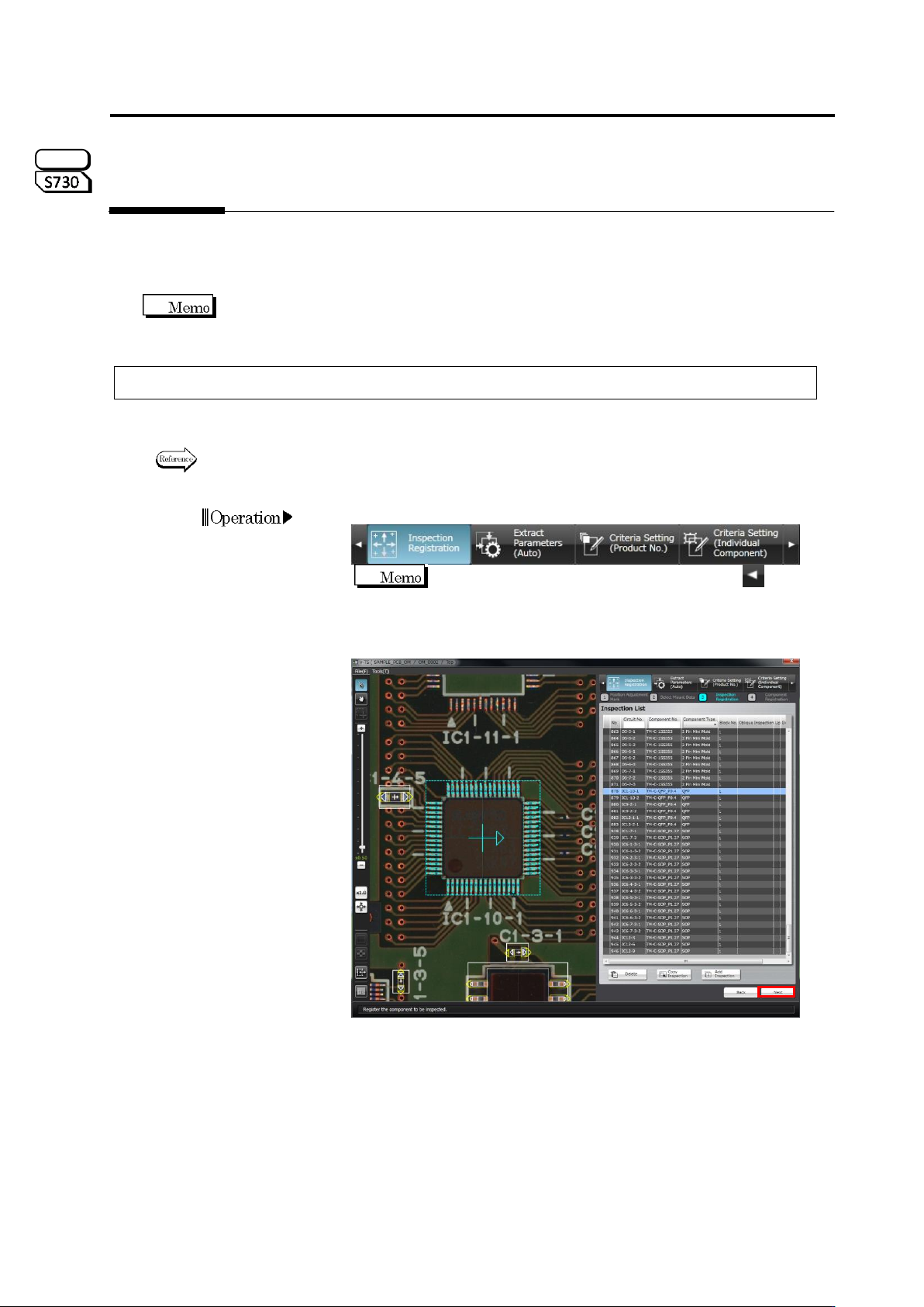
Select the [Inspection Registration] tab.
If the [Inspection Registration] tab is hidden, click at the
left to display it.
2.
The display moves to the Inspection Registration screen. Click
[Next].
S720A
Chapter 2 Inspection Programming
2-110
3.
The Component Registration screen is displayed. Select the
component number for oblique inspection in the Component
Number List, and select "Yes" in the oblique inspection row in the
PCB Information panel.
The component cannot be set to "Yes", if the component type is
"BGA/CSP" or "Others (Bottom Electrode)".
4.
If the PCB test has not been conducted for the inspection program,
conduct the PCB test.
Unless the PCB test has been conducted, it is not allowed to capture
oblique images.
For the procedure to conduct the PCB test, refer to Section
エラー
!
参
照元が見つかりません。
“Testing Using PCBs.”
5.
Save the inspection program.
Refer to "2.11.1 Saving an Inspection Program" for the procedure to
save the inspection program.
6.
Exit inspection program editing and capture oblique image with the
inspection system.
If the inspection program is in the process of editing with v-TS, the
program cannot be opened on the system to capture oblique image.
Refer to "2.14 Quitting Program Editing" for the procedure to exit
inspection program editing.
Refer to the Operation Manual of inspection machine: P3-10 "3.2.4
Capturing Oblique Image" for the procedure to capture oblique image.
削除
: 2.8.1
2.9 Setting Oblique Inspection
2-111
2.9.2 Setting Criteria for Oblique Inspection Items
This section describes the procedure to specify the criteria for oblique inspection.
1.
After capturing oblique image with the system, select the inspection
program in the Select PCB screen on v-TS, and click [Edit].
2.
Select an adjustment image with oblique to perform a PCB test.
3.
Select the [Criteria Setting (Product No.)] tab to display the Criteria
Setting screen.
If the [Criteria Setting (Product No.)] tab is hidden, click at
the left to display it.
4.
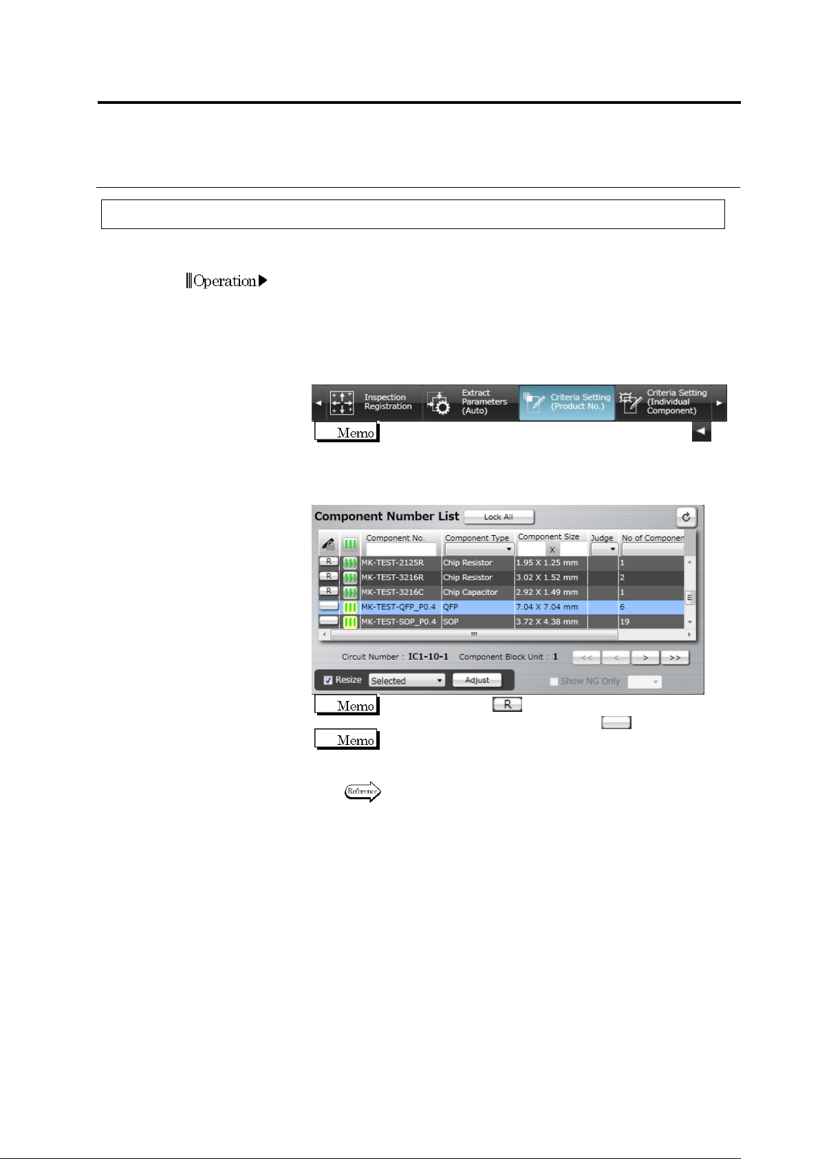
Select the component number for oblique inspection in the
Component Number List.
When the status is (locked), click it to change the
component number state to not locked .
The progress signal is shown in the light yellow background in
the Component Number List for oblique inspection target
component numbers.
Refer to (5) Information Display Area of "2.1.2 Configuration of
the Editing Screen" for details on the progress signals.