MR8740、MR8741_user_manual_eng_20191016H.pdf - 第143页
6.5 Magnifying and Compressing Waveforms 131 5 Chapter 6 W aveform Screen Monitoring and Analysis 6 Description About logic wav eform display When the Zoom function i s enabled, and the log ic waveform display position i…
6.5 Magnifying and Compressing Waveforms
130
This applies to the Memory function only.
A magnified section of a waveform can be displayed together with the unmagnified view by splitting
the screen horizontally.
With the waveform displayed normally on the upper half of the screen, a section magnified along the
time axis can be displayed on the lower half.
6.5.2 Zoom Function (Magnifying a Section
of the Horizontal Axis (Time Axis))
Normal Display
Zoomed Display
Normal Display
Zoom
Procedure
To open the screen: Right-click and select [DISP] Waveform screen
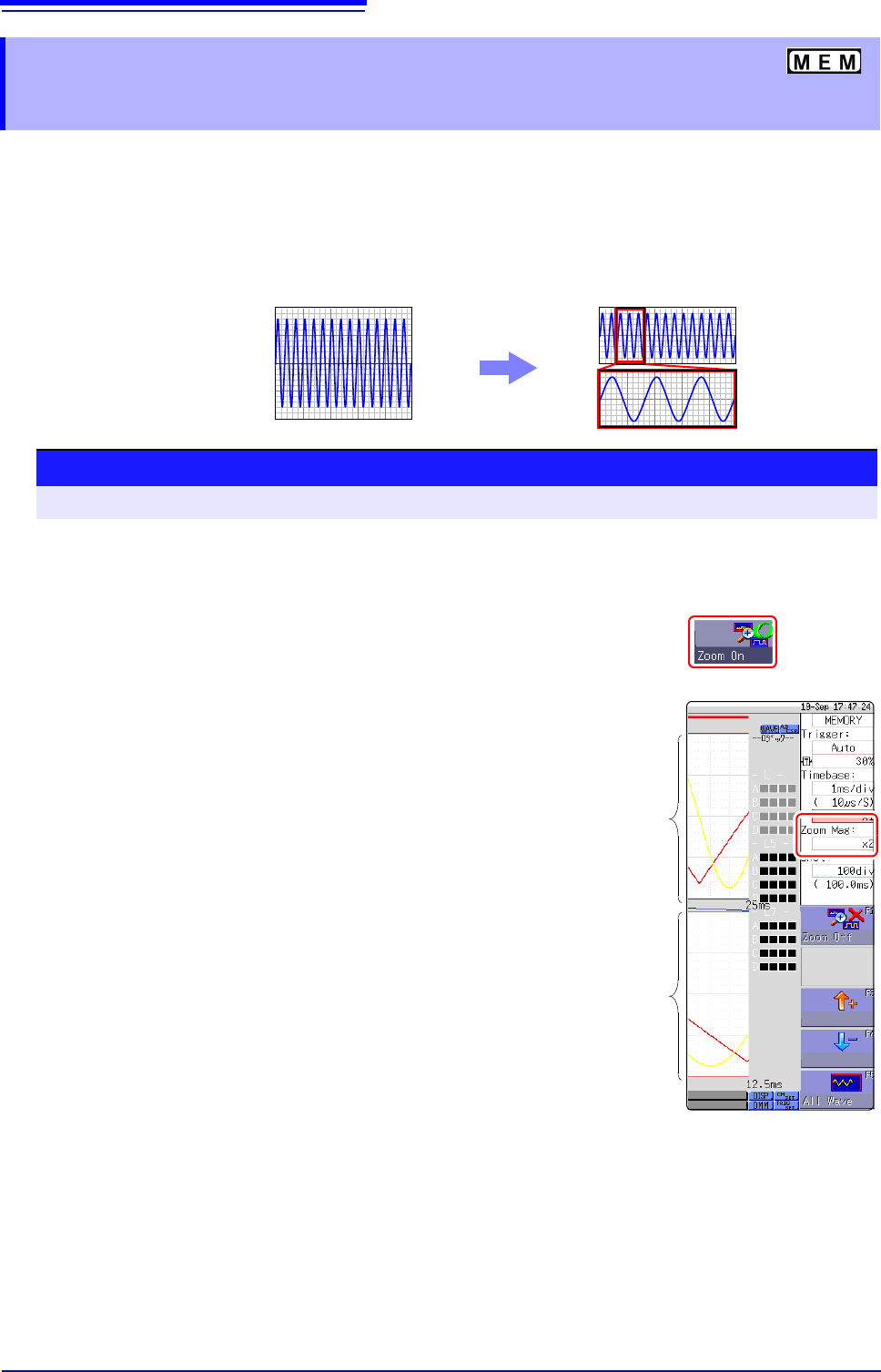
1
Move the mouse cursor to the magnification setting field
under the time axis range, and click it to display [Zoom On].
2
Select [Zoom On].
The Zoom function is enabled and the screen is split into upper and lower
halves.
(Upper: waveform to be magnified, Lower: magnified (zoomed) section of
waveform)
3
Select display magnification for the zoomed waveform sec-
tion.
Move the flashing cursor to the [Zoom Mag], and set the
magnification.
The zoomed waveform section at the lower half of the screen is magnified.
When the same value or a smaller value than the magnification/compression
ratio is specified, the ratio is automatically set to a setting one step higher
than the [Zoom Mag] setting.
4
Scrolls the zoomed section of the waveform.
See: "6.3.2 Scrolling the Measurement Waveform" (p.125)
To cancel Zoom:
Click the magnification, and select [Zoom Off]. (The condi-
tion is canceled while keeping the inherited zoom ratio.)
Example: When the zoom ratio was set to x5 and zoom is
canceled, the ratio setting will be [x5].
Magnifying
and Com-
pressing
ratio wave-
form
Zoom ratio
waveform
6.5 Magnifying and Compressing Waveforms
131
5
Chapter 6 Waveform Screen Monitoring and Analysis
6
Description About logic waveform display
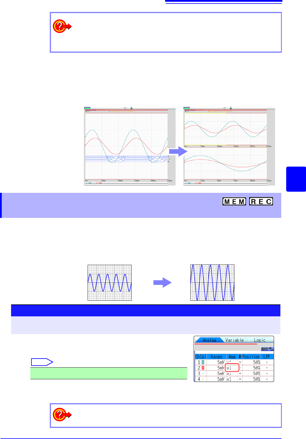
When the Zoom function is enabled, and the logic waveform display position is at
less than [50pos], the logic waveform will not be displayed.
Example: Display position [30pos]
This applies to the Memory function and Recorder Function.
Waveforms on each channel can be magnified or compressed along the vertical axis (voltage axis)
for display.
Magnification and compression based on zero position.
To view the entire waveform (Memory function only)
Move the flashing cursor to the ratio item in the settings window and select [All
Wave].
The waveform information for the entire recording length is displayed.
Normal Display Zoomed Display
6.5.3 Magnifying and Compressing
Vertical Axis (Voltage Axis)
Normal Display
Magnified Display
Procedure
To open the screen: Right-click and select [DISP] Waveform screen Right-click and select [CH.SET]
Channel settings window ([Analog] sheet)
Move the flashing cursor to the [Mag] item of the channel to
adjust, and click it.
Select
Selecting [Invert] will invert plus and minus in the waveform.
See: "7.7 Inverting the Waveform (Invert Function)" (p.159)
x1/10, x1/5, x1/2, x1, x2, x5, x10, x20, x50, x100
To display at an arbitrary ratio
See: "7.5 Variable Function (Setting the Waveform Display Freely)" (p.155)
6.6 Monitoring Input Levels (Level Monitor)
132
All input waveform levels can be monitored in real time.
Analog channels and logic channels can be displayed at the same time.
6.6 Monitoring Input Levels (Level Monitor)
6.6.1 Level Monitor
Procedure
To open the menu: Right-click and select [DISP] Display Menu
Analog channel level
To hide the level monitor
Select [Monitor] again.
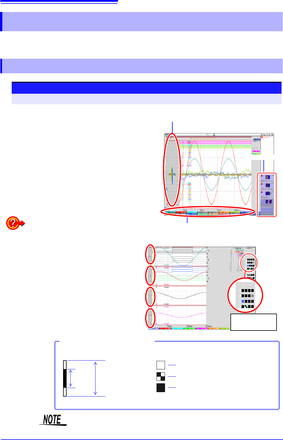
Selecting [Monitor] displays the analog channel level
on the left of the Waveform screen, the logic channel
level on the right of the Waveform screen, and the
monitor numerical values at the bottom of the Wave-
form screen.
Monitor values of analog channels
(Up to 6 digits are displayed.)
Display menu
Display format 2 - 16 screens (p.72)
Level monitors are displayed for each graph.
Upper and lower limit indication is combined with
level monitor.
See: "6.7.1 Showing Upper/Lower Limit On Waveform
Screen" (p.134)
Logic channel
level display
Level display of an analog channel
High
Hi gh& Low
Low
Input
Level
Waveform Display
Range Full Span
Level display of logic channels
How to View a Level Monitor
When the display setting is On,
the part indicated in white takes
the color specified for the wave-
form display. When the setting is
Off, the part becomes gray. The
part indicated in black takes the
background color.
Input levels are not displayed for channels having no corresponding module
installed.