MR8740、MR8741_user_manual_eng_20191016H.pdf - 第28页
1.2 Names and Functions o f Parts 16 1.2 Names and Functions of Part s MR8740 Front Rear V arious Modules (p.36) , (p.39) (For details, see the in struction manual of the respective module.) Power Inlet Connect the suppl…
1.1 Product Overview
15
1
Chapter 1 Overview
The Memory HiCorder is easy to operate and allows quick and efficient measurement and analysis.
Major applications include error monitoring and inspection lines. The product offers the following
features.
Overview Chapter 1
1.1 Product Overview
Simultaneous multi-chan-
nel measurement
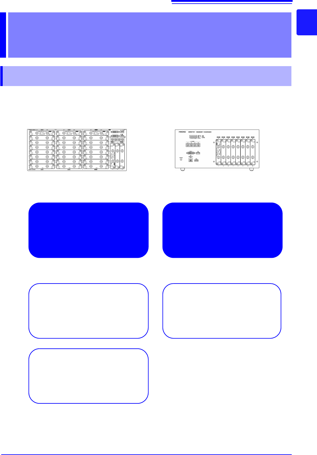
Measure up to 54 analog channels.
Ideal for mounting in a rack
Height: 4U (178 mm) or less
All channels isolated
High-speed sampling: 20 MS/s
Enables responsive evaluation and analysis.
MR8740 MR8741
Multi-channel waveform genera-
tion
1.2 Names and Functions of Parts
16
1.2 Names and Functions of Parts
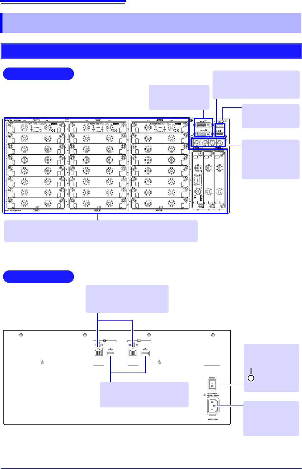
MR8740
Front
Rear
Various Modules (p.36), (p.39)
(For details, see the instruction manual of the respective module.)
Power Inlet
Connect the supplied
power cord here.
(p.55)
POWER Switch
Turns the instru-
ment on and off.
: Power On
: Power Off
(p.56)
100BASE-TX Connector
Connect LAN cables here.
(p.313)
DVI-D Connectors
Connect an LCD
monitor here.
Standard LOGIC
Terminals
Input connectors for
optional logic probes.
(p.39)
USB Connector (Type A)
Connect USB memory sticks here.
(p.53)
Power Indicator
Lit when the instru-
ment is on.
USB Connector (Type A)
Connect USB memory sticks here.
(p.53)
1.2 Names and Functions of Parts
17
1
Chapter 1 Overview
MR8741
Rear
Various Modules
(p.36), (p.39)
(For details, see the instruc-
tion manual of the respective
module.)
100BASE-TX Connector
Connect a LAN cable here.
(p.313)
Standard LOGIC
Terminals
Input connectors for
optional logic probes.
(p.39)
Power Indicator
Lit when the instru-
ment is on.
DVI-D Connector
Connect an LCD
monitor here.
USB Connector (Type A)
Connect USB memory sticks here.
(p.53)
Manufacturer's Serial No.
*
Shows the serial number.
Required for production control. Do not peel off the label.
POWER Switch
Turns the instrument on and off.
: Power On
: Power Off (p.56)
Power Inlet
Connect the supplied
power cord here.
(p.55)
Ventilation Holes (Fan)
Make sure the ventilation
holes are not obstructed.
Front
External control terminals
Input any external sampling signal
here. (p.336)
Allows control of the instrument.
*: The serial number consists of 9 digits. The first two
(from the left) indicate the year of manufacture, and
the next two indicate the month of manufacture.