MR8740、MR8741_user_manual_eng_20191016H.pdf - 第82页
3.4 Setting Measurement Configuration 70 Set the length (number of divisions) to record each time data is acquired. 3.4.3 Recording Length (number of divisions) Procedure To open the screen: Right-click and select [DISP]…
3.4 Setting Measurement Configuration
69
3
Chapter 3 Measurement Procedure
The sampling rate is automatically set to 1/100 of the selected time axis range.
If MR8990 Digital Voltmeter Unit is installed, the sampling rate for the chan-
nels of that unit is set to 1/50.
Example: When 8966 is installed on unit 1 (channels 1 and 2) and MR8990 on
unit 2 (channels 3 and 4), and the time axis is set to 1 s/div
Sampling rate of unit 1 (8966): 10 ms
Sampling rate of unit 2 (MR8990): 20 ms
_______________________________________________________________
• The timebase and sampling rate can be set independently. The sampling rate
is selected depending on the timebase setting.
• When the following timebase values are selected, displayed waveforms are
compressed in the horizontal (time axis) direction as shown.
20 ms/div x1/2
10 ms/div x1/5
_______________________________________________________________
Common
To minimize noise during measurement
If the sampling rate is set too fast, when the input waveform ampli-
tude is small, the difference between maximum and minimum values
may become quite large as a result of sudden impulses such as
noise. To prevent such phenomena, select a slower sampling rate or
enable the module's lowpass filter (p.76).
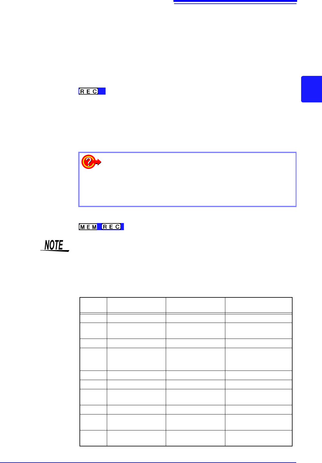
The data refresh rate is not allowed to exceed the maximum sampling rate of the
module.
During the period when data are not updated, the same data are measured,
resulting in a stair-shaped waveform. Even when the same signal is input simul-
taneously by two units, the data may differ due to differences in sampling rate,
frequency bandwidth, and frequency response.
Data refresh rate for various units
Module Max. timebase
Max. sampling rate or
data refresh rate
Reference information
8966 5 s/div 50 ns (20 MS/s) -
8967
Dependent on data re-
fresh setting
Dependent on data re-
fresh setting
See: "7.9.3"(p.163)
8968 100 s/div 1 s (1 MS/s) -
8969,
U8969,
U8979
500 s/div 5 s (200 ks/s) -
8970 Dependent on setting Dependent on setting See: "7.9.5"(p.166)
8971 100 s/div 1 s (1 MS/s) See: "7.9.6"(p.169)
8972
Dependent on re-
sponse setting
Dependent on re-
sponse setting
See: "7.9.7"(p.170)
8973 5 s/div 50 ns (20 MS/s) -
MR8990
Dependent on NPLC
setting
Dependent on NPLC
setting
-
U8974
Dependent on NPLC
setting
Depends on response
setting
See: "7.9.9"(p.173)
3.4 Setting Measurement Configuration
70
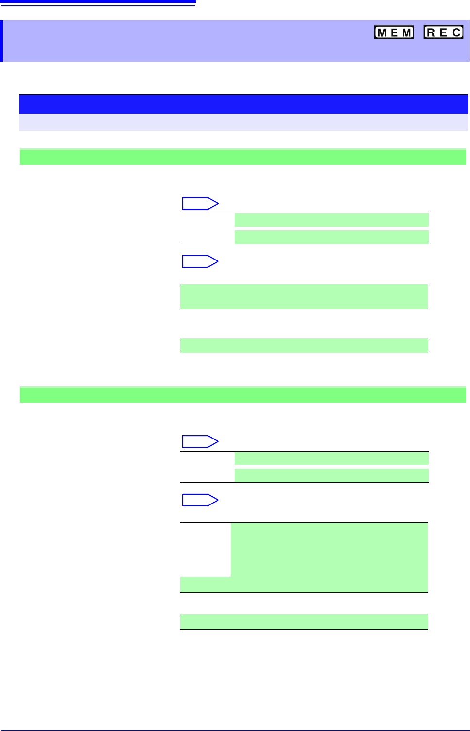
Set the length (number of divisions) to record each time data is acquired.
3.4.3 Recording Length
(number of divisions)
Procedure
To open the screen: Right-click and select [DISP] Waveform screen
Memory Function case
1
Move the flashing cursor to the [Shot] item, and then left-click.
2
Select the type.
Select
3
Set the recording length.
Select
(Fixed Shot)
(User Shot)
Can be inputted by the numeric keypad on the STATUS
screen.
See: "7.1.3 Alphanumeric Input" (p.141)
Fixd Shot Select from a a range of preset values.
User Shot
Freely specify any value in 1-division units.
25, 50, 100, 200, 500, 1000, 2000, 5000, 10000, 20000, 50000, 100000
div
1 to 160000 div
Recorder Function case
1
Move the flashing cursor to the [Shot] item.
2
Select the type.
Select
3
Set the recording length.
Select
(Fixed Shot)
(User Shot)
Can be inputted by the numeric keypad.
See: "7.1.3 Alphanumeric Input" (p.141)
Fixd Shot Select from a a range of preset values.
User Shot
Freely specify any value in 1-division units.
Cont. When [On] is selected, measurement is carried out while
continuously overwriting data in memory.
Data from the point at which measurement was stopped
to the maximum recording length can be saved or print-
ed again.
25, 50, 100, 200, 500, 1000, 2000, 5000, 10000, 20000, 50000 div
1 to 80,000 div
3.4 Setting Measurement Configuration
71
3
Chapter 3 Measurement Procedure
Description
Recording Length and Data Samples
Each division of the recording length consists of 100 data samples. The total
number of data samples for a specified recording length = set recording length
(divisions) × 100 + 1.
However, if MR8990 Digital Voltmeter Unit is installed, the number of data sam-
ples is as follows.
• When only MR8990 is installed
Number of data samples for each division: 50 data samples
Total number of data samples for recording length: Set recording length (divi-
sions) × 50 + 1
• When a mix of MR8990 and another units is installed
Channel of MR8990
Number of data samples for each division: 50 data samples
Total number of data samples for recording length: Set recording length (divi
sions) × 50 + 1
Channel of other units
Number of data samples for each division: 100 data samples
Total number of data samples for recording length: Set recording length (divi-
sions) × 100 + 2
• Each recording length division = 100 pairs of data points, with each pair com-
posed of two values: the maximum and minimum measured values within
each sampling period. The resolution of the data measured by the recorder
function is 16bit.
When recording length is set to [Cont.]
• Data for up to 80,000 divisions from the end of measurement can be recorded
in the internal memory of the unit.
The instrument stores the maximum recording length of data back from the
point at which measurement was stopped in its internal memory (80,000 divi-
sions).
• When Auto-saving is On, the saving is not performed during the measure-
ment. At the forced shutdown point, the remaining data in memory will be
saved.
To change recording length while measuring
Recording length can be changed on the Waveform screen.
The measurement will restart with the newly set recording length.