MR8740、MR8741_user_manual_eng_20191016H.pdf - 第177页
7.9 Setting Details of Modules 165 6 Chapter 7 Utility Functions 7 The 8969 Strain Unit and U896 9 Strain Unit can perform auto balance. When auto balance is perfor med, the re ference outp ut level of the conversion uni…

7.9 Setting Details of Modules
164
Renew Data
(Data Refresh)
The data refresh rate can be set to Fast, Normal, or Slow.
The default setting is [Normal]. This allows stable measurement while removing
noise. For quicker response, select [Fast], but note that this will make the mea-
surement more susceptible to noise. For further improved measurement stability,
select [Slow].
Select
Selections Description
Fast
Data are updated approximately every 1.2 ms.
Normal
Data are updated approximately every 100 ms. (default setting)
Slow
Data are updated approximately every 500 ms.
7.9 Setting Details of Modules
165
6
Chapter 7 Utility Functions
7
The 8969 Strain Unit and U8969 Strain Unit can perform auto balance.
When auto balance is performed, the reference output level of the conversion
unit can be matched with the specified zero position.
It is applicable only to a 8969 Strain Unit and U8969 Strain Unit.
Before executing auto-balance ___________________________________
• Turn power on and wait 30 minutes to allow the internal temperature of the
module to stabilize.
• After connecting a strain gauge transducer to the module and a measuring
target,execute the autobalance without any input including distortion.
• Auto-balance cannot execute during measurement.
• Mouse operations are not accepted while auto-balance is executing.
To execute auto-balance_________________________________________
See: Opening the [Each Ch] sheet, Making a Channel Selection (p.161)
Auto Balance can also be executed from the Channel settings window (Analog
sheet) (if the range of a channel with installed strain unit is selected).
See: Opening the Channel settings window ([Analog] sheet): (p.76)
In the following cases, auto-balance should be executed again.
• After changing the vertical axis (strain axis) range
• After a module has been removed or inserted
• After the strain gauge transducer has been replaced
• After power has been turned off and on
• After performing a system reset
• When ambient temperature has changed significantly (the zero position may
drift)
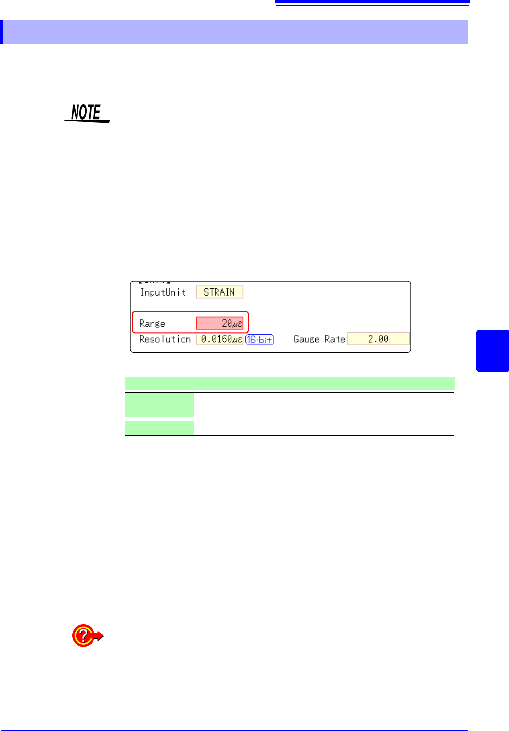
7.9.4 Setting Model 8969 and U8969 Strain Unit
The instrument describes Model U8969 as “8969”.
Setting Item: [Range]
Selections Description
Auto Bal All
Chs
Auto-balance will be executed for all channels where a Model 8969
or U8969 Strain Unit is installed.
Auto Bal Ch 1
Auto-balance will be executed for the currently selected channel.
If "Warning: Auto balance failed." appears:
The channel on which auto-balance failed is displayed.
Verify the following, and execute again:
• Is the strain gauge transducer in a discharged state? (Make sure that it is not
being subject to vibration, etc.)
• Is the strain gauge transducer correctly connected to a measuring target?
7.9 Setting Details of Modules
166
See: Opening the [Each Ch] sheet, Making a Channel Selection (p.161)
Mode Changes the measurement mode.
Select
VRange
(Input voltage)
Set the maximum level for the input signal.
Select
Threshold • When the measurement waveform exceeds the threshold value, the measure-
ment value is acquired based on the time interval and the number of times the
threshold was exceeded.
• The threshold value upper and lower limits and increases and decreases in
width depend on the input voltage ([VRange]) setting.
• While setting the threshold, the voltage level is displayed on the level monitor.
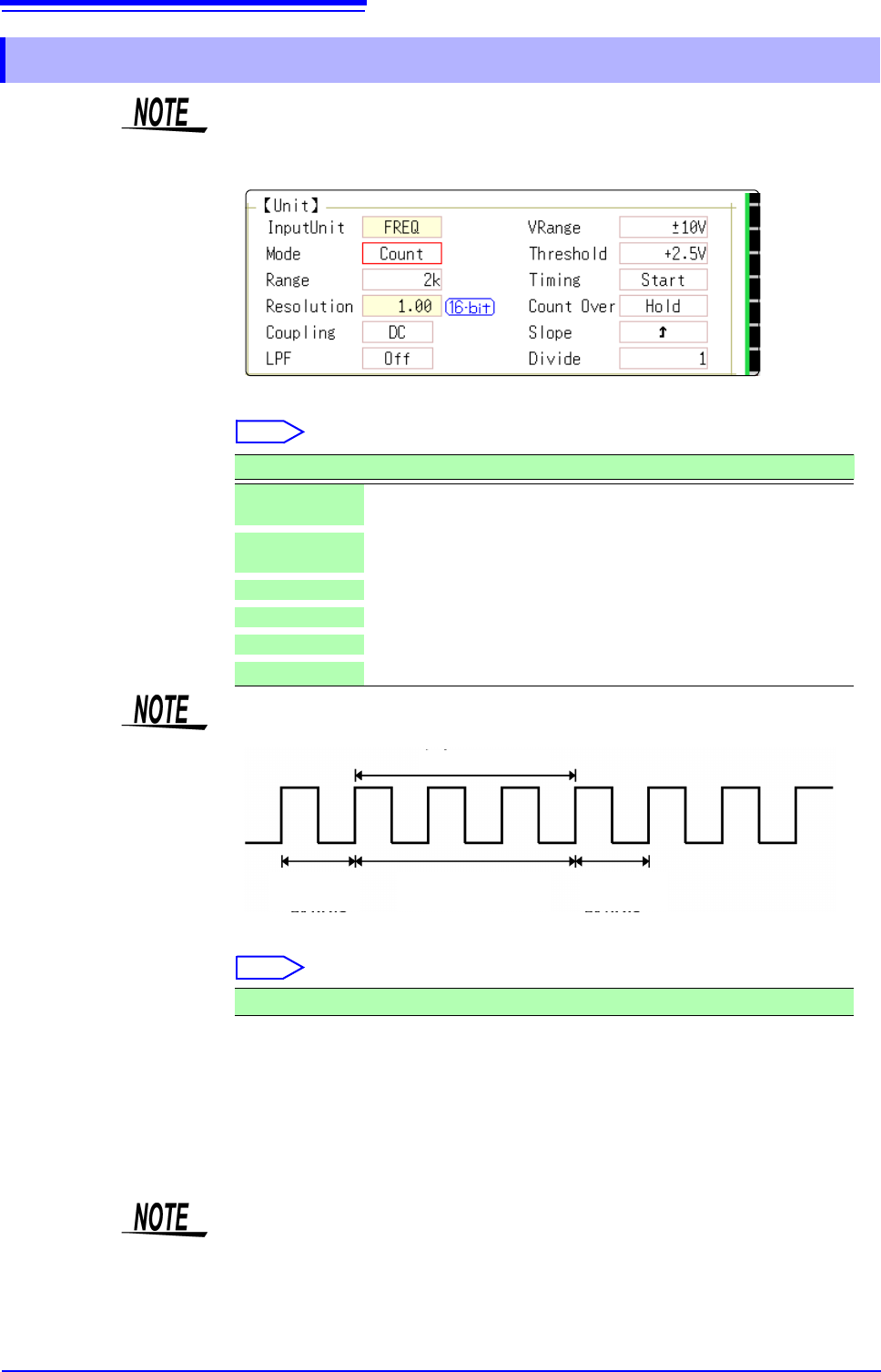
7.9.5 Setting Model 8970 Freq Unit
When the display of standard logic channels (LA and LB) is on, the 8970 Freq
Unit installed on unit 1 can no longer be used.
Selections Description
Frequency
Measure the frequency of the measurement waveform (Hz hertz)
(default setting)
RPM
Measure the number of rotations of the measurement target (r/min
rotations/minutes)
P-Freq
Measure the power frequency variation (Hz hertz)
Count
Add up the number of input pulses
Duty
Measure the duty rate of the measurement waveform (% percent)
Pulse Width
Measure the pulse width (s second)
Pulses with rises during dead time (calculation) (25 kHz or higher) cannot be
measured.
Waveform
loaded
Waveform
loaded
Calculation (40 s)
Ignored
±10 V (default setting), ±20 V, ±50 V, ±100 V, ±200 V, ±400 V
To prevent measurement errors due to noise, the threshold has a hysteresis of
approximately 3% versus the input voltage. (When
[VRange] is [ ±10 V], it is
around ±0.3 V.)
Set a threshold in excess of the hysteresis width versus the voltage peak.