MR8740、MR8741_user_manual_eng_20191016H.pdf - 第61页
2.2 Connecting Cords 49 2 Chapter 2 Measurement Prep arations Applicable Modules • Model MR8990 Digital V oltmeter Unit Cables to connect: L2200 Test Lead • L2200 T est Leads (Maximum input voltage: 1000 V) Measuring V o…
2.2 Connecting Cords
48
Use to connect: Logic Probe
• 9320 Logic Probe
*
• 9320-01 Logic Probe
• 9327 Logic Probe
LOGIC terminal
Measuring Logic Signals
Applicable Modules
• Model 8973 Logic Unit
LA to LB (MR8740) and LA to LD
(MR8741) are supplied as standard equip-
ment with the instrument.
Read "Before Connecting a Logic Probe to the Measurement Object" ( p.12) carefully.
For more information about logic probe specifications, see the instruction manual that came with the logic probe you plan to us
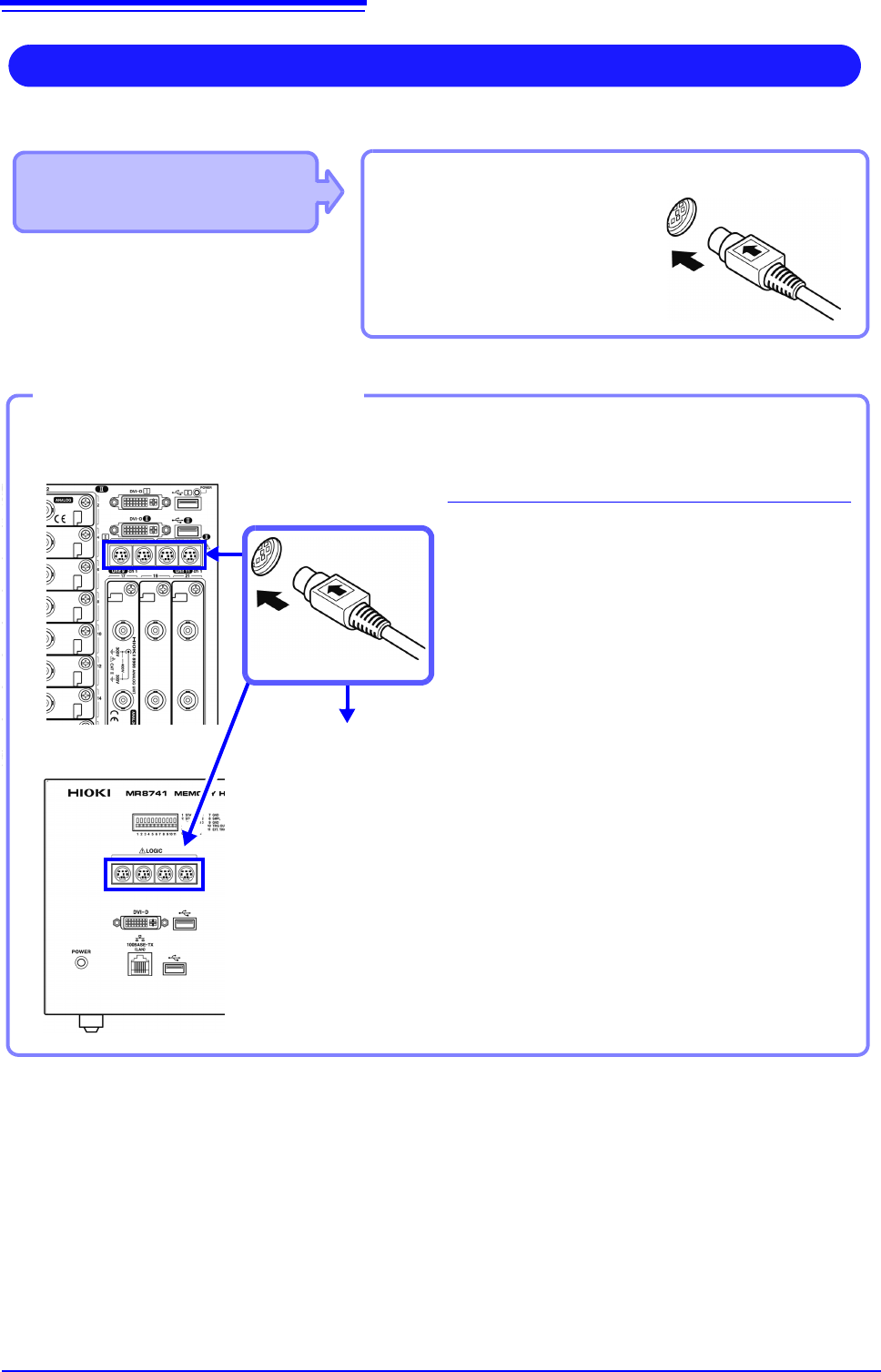
Connect to the measurement object
MR8740 Front Side
Example: Connecting the 9327 Logic Probe
1
Connect the logic probe by aligning the
groves on the plug and a LOGIC terminal.
2
Connect to the measurement object.
Required item:Model 9327 Logic Probe
LOGIC terminals
2
1
Connect to LOGIC Terminals
MR8741 Front Side
2.2 Connecting Cords
49
2
Chapter 2 Measurement Preparations
Applicable Modules
• Model MR8990 Digital Voltmeter Unit
Cables to connect: L2200 Test Lead
• L2200 Test Leads
(Maximum input voltage:
1000 V)
Measuring Voltage with High Accuracy (Digital Voltmeter)
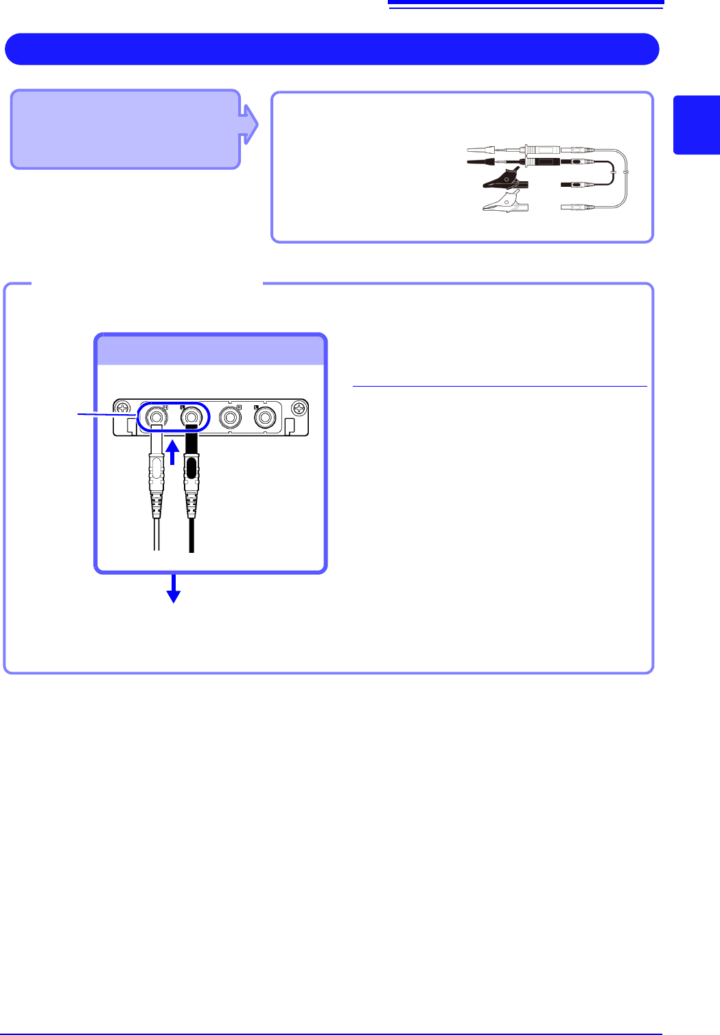
Connect to the banana jacks on a module.
1
Connect the test leads to the banana
jacks on the module.
Connect the black lead to the L jack, and
the red lead to the H jack. Make sure the
test lead plugs are fully inserted into the
jacks.
2
Connect the test leads to the object to
be measured.
Required item: Test leads above
Banana jacks
Connect to banana jacks
Connect the leads to the object to
be measured
Connecting the test leads
1
2
Red
Black
2.2 Connecting Cords
50
Applicable Modules
• Model U8974 High Voltage Unit
Required item: Model L4940 Connection Cable Set
• Model L4940 Connection Cable Set:
(Maximum input voltage: 1000 V)
High Voltage Measurement
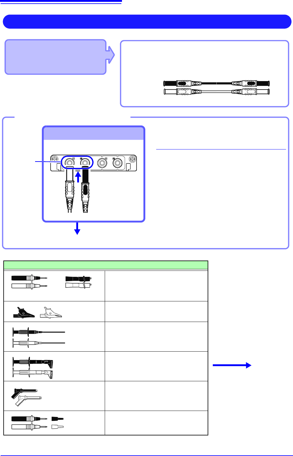
Connect to the banana jacks on a module.
1
Connect the plug of the connection
cable to the banana jacks on the
module.
Connect the terminal and the plug of the
same color.
2
Insert the accessory clip into cable
clips.
3
Connect the cable clips to the mea-
surement object.
Required item: Model L4940 Connection Cable Set
Banana jacks
To Connect to banana jacks
Connect the clip.
Connect the Connection cable
Accessory clips
Model L4934 Small Alligator Clip Set
* Model L4932 is required when using
Model L4934.
Model L4935 Alligator Clip Set
Model 9243 Grabber Clip
Model L4936 Bus Bar Clip Set
Model L4937 Magnetic Adapter Set
Model L4932 Test Pin Set
L4934
+
Connect to the mea-
surement object.
Red
Black
3
1
2