MR8740、MR8741_user_manual_eng_20191016H.pdf - 第185页
7.9 Setting Details of Modules 173 6 Chapter 7 Utility Functions 7 See: "Opening the [Each Ch] sheet, Making a Channel Sele ction" (p.161) Mode Switches betw een voltage measureme nt and RMS measurement. Select…

7.9 Setting Details of Modules
172
Select
Selections Description
Off
Calibration and synchronization are not performed.
On
Performs calibration and synchronization.
Synchroniza-
tion
Performs only synchronization between channels.
• The calibration time is approximately 150 ms. That period becomes a waiting
time in which measurement is not performed.
• If synchronization between channels is performed, a signal to stop integration
is sent to each unit when measurement is started and the wait process is per-
formed until the first integration finishes. The wait time required for this process
is (10 ms + integration time
*
).
*The integration time varies depending on the NPLC setting.
If synchronization is not performed, the above wait time will also be required
for measurement performed immediately after the settings of the Digital Volt-
meter Unit are changed. However, there will be no wait time when measure-
ment is performed with the same settings.
• When this is set to OFF (default setting), perform calibration manually.
See:"2.7 Performing Calibration (When Mounting MR8990)" (p.59)
7.9 Setting Details of Modules
173
6
Chapter 7 Utility Functions
7
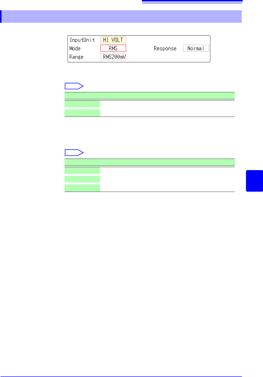
See: "Opening the [Each Ch] sheet, Making a Channel Selection" (p.161)
Mode Switches between voltage measurement and RMS measurement.
Select
Response The response time for RMS measurement can be set to three speeds: Fast, Nor-
mal and Slow.
The response time can be set to [Slow] to stabilize the measured value when
the frequency is low or when severe fluctuations are present.
Select
7.9.9 Setting Model Model U8974 High Voltage Unit
Selections Description
DC
Voltage measurement (Default setting)
RMS
RMS measurement
Selections Description
Fast
Response time is set to 150 ms.
Normal
Response time is set to 500 ms. (Default setting)
Slow
Response time is set to 2.5 s.
7.9 Setting Details of Modules
174
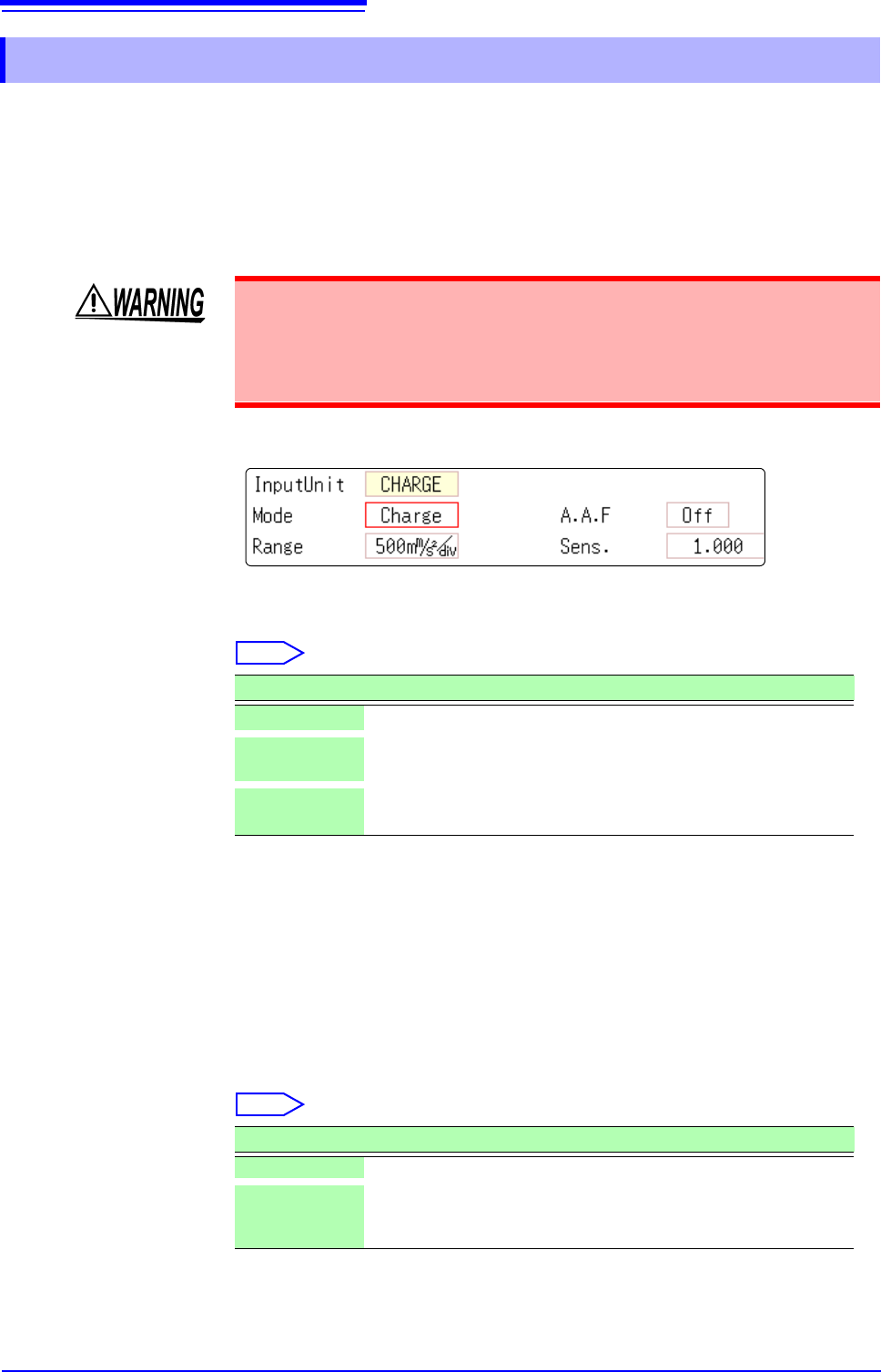
This setting allows you to choose between voltage measurement and accelera-
tion measurement (chargeoutput or built-in pre-amplifier) for a channel.
A channel can measure either one of them.
[Voltage] mode and [PreAmp] mode use BNC connectors, whereas [Charge]
mode uses miniature connectors.
Model U8979 can automatically recognize TEDS-compliant
*
sensors.
*: Transducer electronic data sheet
See: "Opening the [Each Ch] sheet, Making a Channel Selection" (p.161)
Mode Switches the measurement mode.
Select
(When setting mode to [PreAmp])
Move the cursor to the [Sens.] box and execute [TEDS Load].
Acquires sensitivity of a connected sensor. However, the instrument can acquire
sensitivity of TEDS-compliant acceleration sensors with a built-in pre-amplifier
only.
When sensor sensitivity has been acquired, it is automatically set.
A.A.F The anti-aliasing filter can prevent aliasing distortion that may be produced dur-
ing FFT calculation. The cutoff frequency automatically changes according to the
sampling rates or frequency range (for the FFT function) settings.
Select
7.9.10 Setting Model U8979 Charge Unit
Setting the measurement mode to [PreAmp] allows Model U8979 Charge Unit
to constantly provide power (3.5 mA, 22 V) to sensors. Set any measurement
mode other than [PreAmp] or tum off the instrument before connecting a sensor
or probe with a BNC terminal to avoid an electric shock or damage to the mea-
surement target.
Mode Measurement target Measurement sensitivity
Voltage
Voltage —
Charge
(Default setting)
Charge-output acceleration
sensor
0.1 pC/(m/s
2
) to 10 pC/(m/s
2
)
PreAmp
Acceleration sensor with a
built-in preamplifier
0.1 mV/(m/s
2
) to 10 mV/(m/s
2
)
Selections Description
OFF Disables the anti-aliasing filter. (Default setting)
ON Enables the anti-aliasing filter.
(Disabled when the external sampling is used, or the sampling rate
is set at 100 kS/s or faster)