MR8740、MR8741_user_manual_eng_20191016H.pdf - 第53页
2.2 Connecting Cords 41 2 Chapter 2 Measurement Prep arations Applicable Modules • M odel 8970 F req Unit Use to connect: Connection cords • L9197 Connection Cord (Maximum input voltage: 600 V) Large alligator clip type …
2.2 Connecting Cords
40
Example: 8966 Analog Unit
Required item: One of the above cables
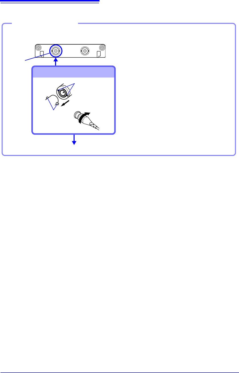
BNC jack
Connect to BNC jack
Lock
Bayonet rugs on
the module
BNC plug slots
Connect to the measurement object
Connecting the cable
1
Connect the BNC plug on the cable to
a BNC jack on the module.
2
Align the slots in the BNC plug with
the guide pins on the jack on the mod-
ule, then push and twist the plug
clockwise until it locks.
3
Connect the cable clips to the mea-
surement object.
Disconnecting BNC connectors
Push the BNC plug, twist it counter-
clockwise, and pull it out.
2.2 Connecting Cords
41
2
Chapter 2 Measurement Preparations
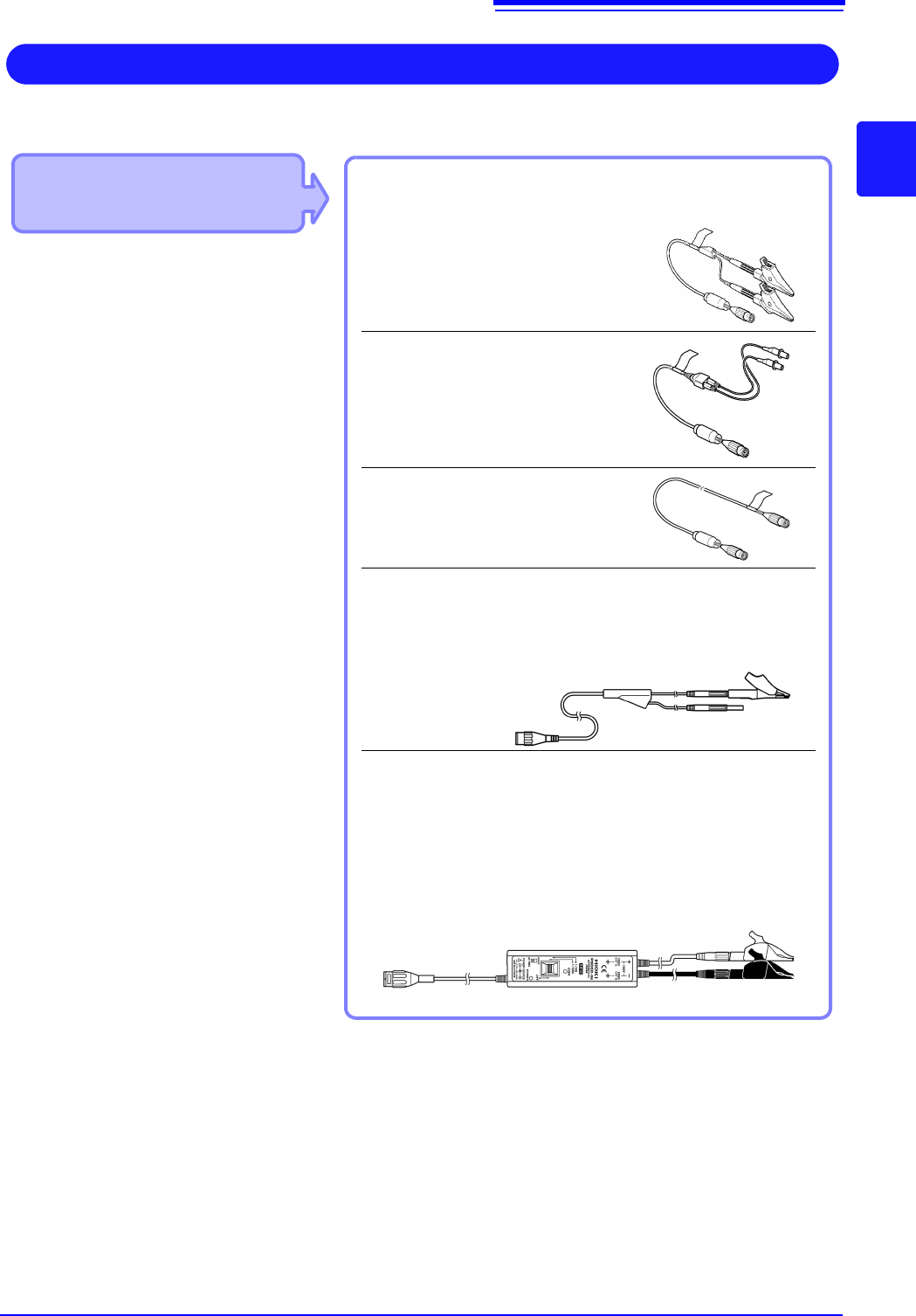
Applicable Modules
• Model 8970 Freq Unit
Use to connect: Connection cords
• L9197 Connection Cord
(Maximum input voltage: 600 V)
Large alligator clip type
• L9198 Connection Cord
(Maximum input voltage: 300 V)
Small alligator clip type
• L9217 Connection Cord
(Maximum input voltage: 300 V)
For measuring BNC output
• IModel L9790 Connection Cord
(Maximum input voltage: 600 V)
Terminal type: Alligator, contact, grabber
Example: Terminal type: Alligator
IIf the voltage to be measured exceeds the maximum input rating
of the module being used
• Model 9322 Differential Probe
*1
• Model 9665 10:1 Probe
• Model 9666 100:1 Probe
• Model P9000-01/-02 Differential Probe
*2
Example: Model P9000-02 Differential Probe
Measuring Frequency, Number of Rotations and Count
Connect to the BNC jack on a module.
*1 An optional power cord or AC adapter is re-
quired.
*2 An optional AC adapter or a commercially
available USB cable is required.
Refer to (p.40) for details about connecting to BNC terminals.
2.2 Connecting Cords
42
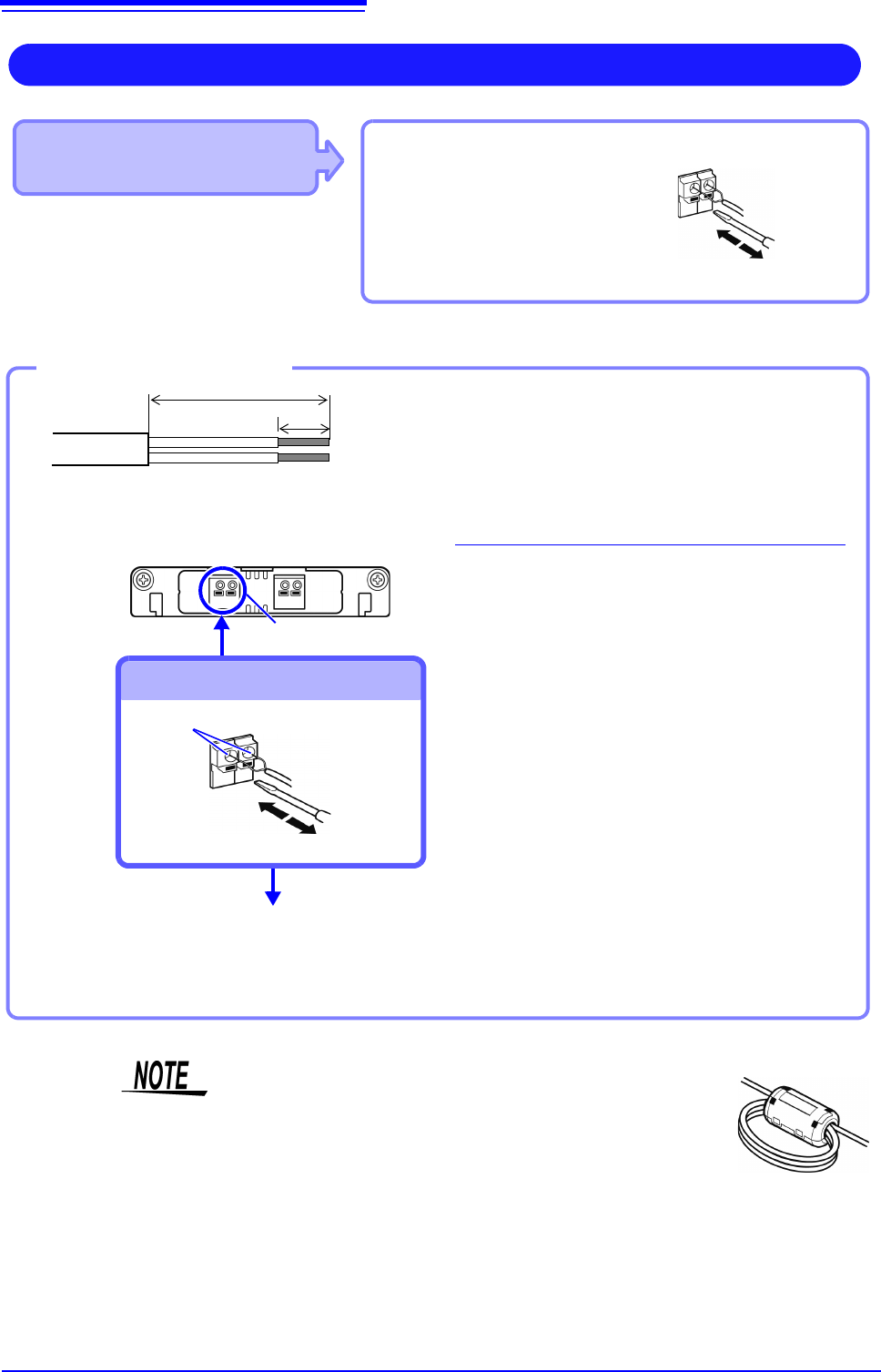
Applicable Modules
• 8967 TEMP Unit
Use to connect: Thermocouple
(Compatible wire: AWG 16 to 26, 0.4
to 1.2 mm diameter)
Connect to terminal block
Measuring Temperature
Connect to the terminal block on the input
module.
Terminal Block
Connection Holes
Insert to terminal block
Outer Insulation
10 mm
25 mm
Thermocouple
single wires
Inner insulation
Attach to the measurement object
Inserting a Thermocouple
2
1
3
4
5
1
Strip insulation from the thermocouple
wires as shown at the left.
Stripping length: approx. 10 mm
2
Push the blade of a flat screwdriver
into the button on the terminal block of
the module.
3
Insert each thermocouple wire into the
appropriate terminal hole while press-
ing the button.
Confirm proper polarity.
4
Release the button.
The thermocouple is connected.
5
Attach to the measurement object.
To remove the thermocouple
Hold the button while pulling the ther-
mocouple wire out.
Required item:
Thermocouple, Ferrite clamp-on choke (8967’s option),
flat-blade screwdriver (2.6-mm blade)
Recommended wire:
Compatible wire:Single-strand thermocouple wire, 0.4
to 1.2-mm diameter
Stripping length:10 mm
If surrounding equipment is affected by noise, coil the ther-
mocouple several times and then attach the included ferrite
clamp-on choke (as seen in the diagram to the right).