MR8740、MR8741_user_manual_eng_20191016H.pdf - 第93页
3.6 Starting and Stopping Measurement 81 3 Chapter 3 Measuremen t Procedure This section explains how to init iate and terminate a measu rement. Click [ST ART] to star t measuring. Click [STOP] to stop reco rding at the …
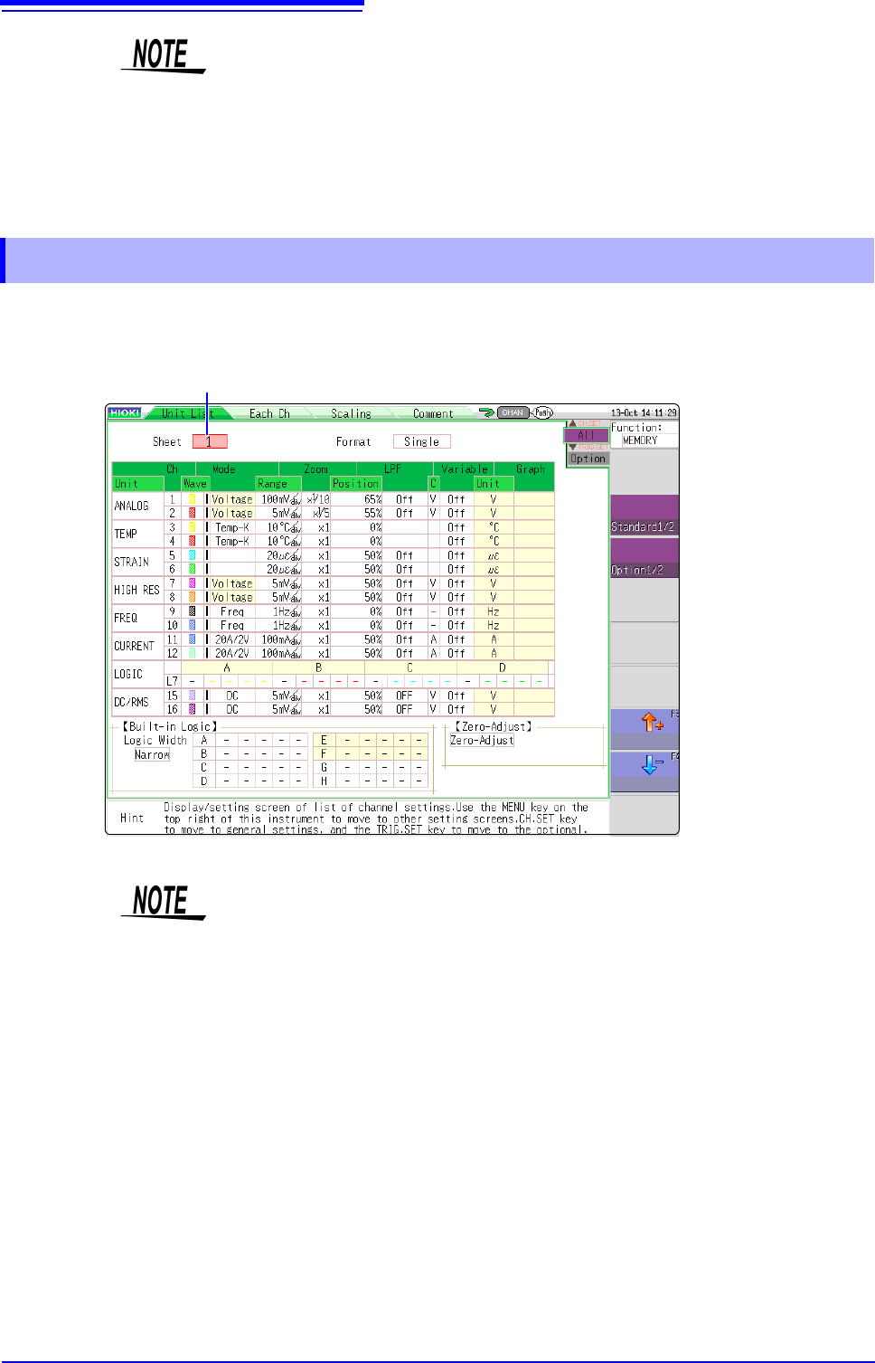
3.5 Input Channel Setting
80
The input channel settings can be set differently for each displayed sheet. Up to four sheets can be set.
You can set desired waveforms for displaying to different sheets and switch them.
You can configure the waveform calculation settings using the channel setting
window.
See: "3.5 Input Channel Setting" (p.73)
• When the standard logic display is on, the 8970 Freq Unit installed on unit 1 or 2 can no
longer be used. Furthermore, the 16-bit resolution 8967 TEMP Unit, 8968 High Resolu-
tion Unit, 8969 Strain Unit, U8969 Strain Unit, U8974 High Voltage Unit, and U8979
Charge Unit have a resolution of 12 bits. Also, when MR8990 Digital Voltmeter Unit is
installed on unit 1 (unit 1 or unit 2 in the case of MR8741), the standard logic can no
longer be used.
• With MR8740, install the logic units on unit 1 to unit 8. Even if you install logic units on
units 9 and after, they will be invalid.
3.5.4 Display Sheet
Sheet switching (1 to 4)
• Only the following display-related settings can be set to each displayed sheet.
Analog waveform: Display ON/OFF, waveform color, ratio, zero position,
graph variable (ON/OFF, upper and lower limit)
Logic waveform: Display ON/OFF, waveform color, display position, and
logic width
X-Y waveform: Display ON/OFF, waveform color, X ch, Y ch, waveform
calculation (X ch, Y ch)
Common setting: Display format
• The measurement-related settings other than above will be common to all dis-
played sheets.
When range is changed, the range of all display sheets is changed.
• When a settings file is saved, the settings of all displayed sheets are saved.
• A waveform file is saved based on the setting of the sheet displayed at the
time of saving. When a waveform file is loaded, only the sheet displayed at the
time of saving can be loaded because other sheets were not saved.
3.6 Starting and Stopping Measurement
81
3
Chapter 3 Measurement Procedure
This section explains how to initiate and terminate a measurement.
Click [START] to start measuring.
Click [STOP] to stop recording at the end of the specified recording length.
Click [STOP] again so stop recording immediately.
The operation conditions for [START] and [STOP] can be changed.
See: "Chapter 14 System Environment Settings" (p.309)
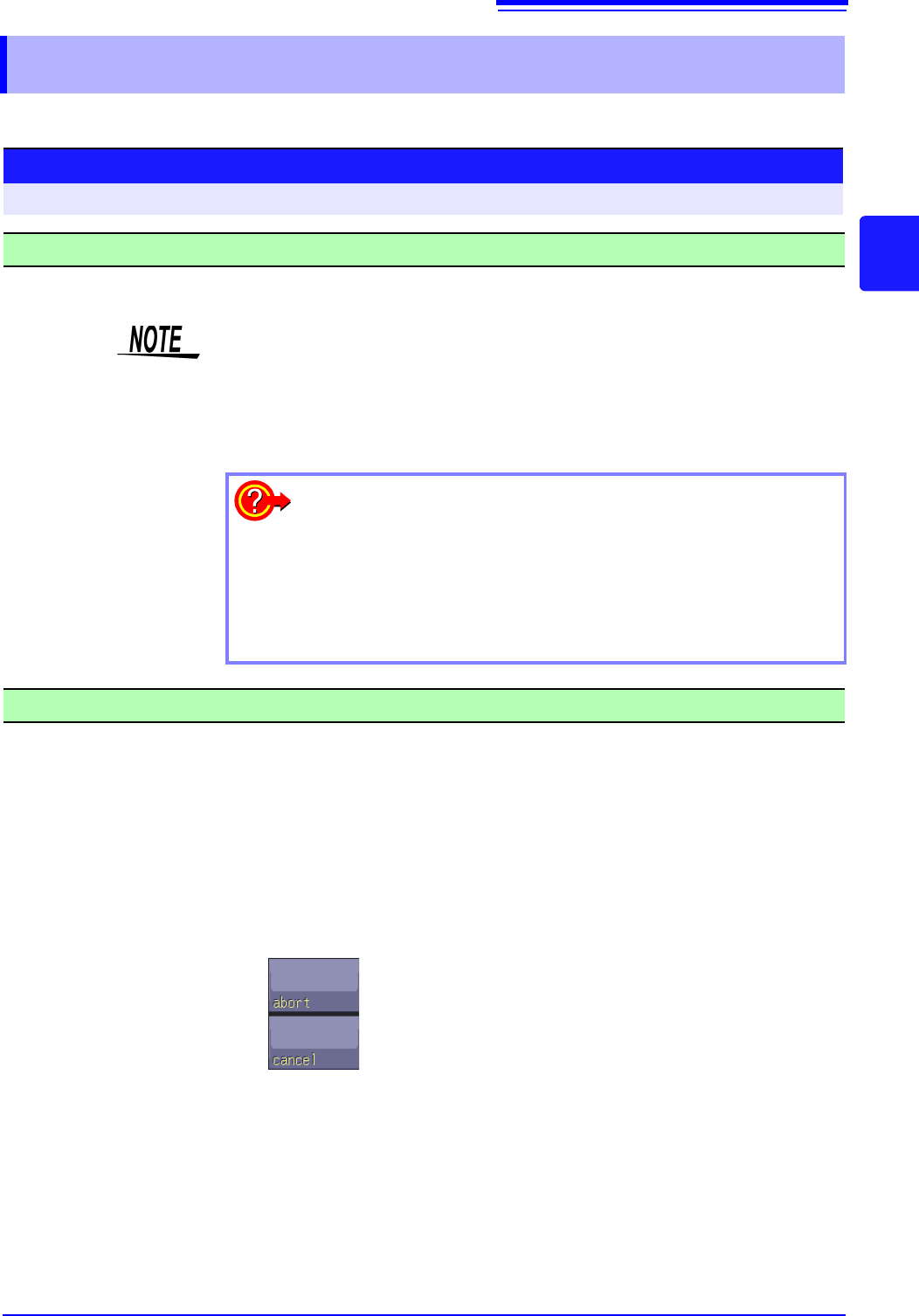
Note When [STOP] is clicked, the following indication may appear on the screen.
3.6 Starting and Stopping Measurement
Starting Measurement
Procedure
To open the screen: Right-click and select [DISP] Waveform screen
• When a measurement is started, waveform data that were displayed on the
screen are cleared. However, when the measurement conditions are the same,
the waveform data for up to 16 past measurements is retained as history.
• Measurement can also be started by inputting a signal at the external control
terminal.
See:"Chapter 16 External Control (MR8741 Only)" (p.335)
To prevent inadvertent measurement start
To reduce the risk of accidentally starting a measurement through an
operation error, operation conditions can be set for [START].
See: "Start Action" (p.311)
To automatically save data during measurement
See: "4.2.2 Automatically Saving Waveforms" (p.88)
Stopping Measurement
The measurement will stop at the point where the mouse is
clicked.
The stopping procedure is canceled and measurement
continues.

3.6 Starting and Stopping Measurement
82
Measurement methods are normal measurement (start recording when measurement starts) and trigger
measurement (start recording when trigger criteria are satisfied). In this manual, "Measurement start"
means the instant when you click
[START], and "Recording start" means the instant when recording begins
on the waveform screen.
• Select the Trigger mode to record upon either single or repeating trigger
events.(p.191)
• Enable pre-triggering if you want to capture data measured prior to trigger
events.(p.204)
When the trigger mode is set to [Repeat] or [Auto] (Memory function only), the
number of trigger events is shown in the top part of the screen (Storage Counter).
See: "Explanation of Screen Contents" (p.20)
Measurement and Internal Operations
Start Measurement
[START]
End of Measurement
Recording
Starts
Recording
Stops
[Now Storing]
[Storing Finished]
[ ]: Status Bar Display
Recording
Normal
Measurement
Without triggering
Terminates when recording length has been recorded.
End of Measurement
[Trigger Wait]
Recording
Starts
T
Recording
Stops
[Now Storing]
Recording starts when a trigger event occurs and continues for the specified recording
length.
Start Measurement
[START]
[Storing Finished]
Recording
Trigger
Measurement
Trigger mode: [Single]
Pre-triggering not enabled
Single triggering
Recording starts when a trigger event occurs, continues for the specified recording length,
and returns to the Trigger Wait state.
Stop Measurement
[STOP]
[Trigger Wait]
Recording
Starts
T
Recording
Stops
[Now Storing]
Start Measurement
[START]
Recording
[Trigger Wait]
T
Recording
Starts
Repeated triggering
Trigger mode: [Repeat]
Pre-triggering not enabled
[Pre-Trigger Wait]
End of Measurement
[Trigger Wait]
Start Measurement
[START]
T
Recording
Stops
[Now Storing]
After starting measurement and internally acquiring data for the specified
pre-trigger period, the Trigger Wait state is activated.
Recording
Starts
The specified pre-trigger wait period is recorded before each trigger event
The data before a trigger event (for the pre-trigger period) is recorded.
Recording
[Storing Finished]
T
Post-trigger waveform
Waveform dur-
ing specified pre-
trigger period
Repeated triggering and recording of phenomena before each event
Trigger mode: [Repeat]
Pre-triggering enabled
Operation is
repeated
from pre-trig-
gering stage.