MR8740、MR8741_user_manual_eng_20191016H.pdf - 第381页
17.6 Specifications of Modules 369 Chapter 17 S pecifications 16 17 General Specifications Pulse Output Specifications Pattern Output Specifications 17.6.14 MR8791 Pulse Generator Unit Temperature and humidity for guaran…

17.6 Specifications of Modules
368
Accuracy figures assume installation in a Memory HiCorder and operation after a 30-minute warm-up period at 23C±5C
(73F±9F) and 80% RH (no condensation).
General Specifications
Voltage Output Specifications
17.6.13 MR8790 Waveform Generator Unit
Product warranty period 3 years
Guaranteed accuracy period 1 year
Guaranteed accuracy period
after adjustment made by Hio-
ki
1 year
Number of output channels 4 channels (all channels isolated from each other and from the enclosure and outputs)
Self-test function Included (with voltage and current monitor)
Voltage and current monitor
function (switchable)
Resolution: 5 A (current monitor)
10 mV (voltage monitor)
Monitor accuracy: ±3.0% f.s. (f.s. = 10 V [voltage monitor] or 5 mA [current monitor])
Maximum output current ±5 mA
Allowable load resistance 2 k or greater
Output terminals SMB terminals
Output configuration Waveform output/open/short circuit
Output relay switching time 5 ms or less
Output protection Output current limited to 40 mA (when output is shorted)
Maximum rated voltage to
earth
33 V AC rms or 70 V DC (between individual output channels and enclosure as well as
between individual output channels)
Anticipated transient overvoltage: 330 V
Operating temperature and
humidity
As per Memory HiCorder into which the MR8790 is installed
Operating environment As per Memory HiCorder into which the MR8790 is installed
Storage temperature and
humidity
-20°C to 50°C (-4°F to 122°F), 90% RH or less (no condensation)
Dimensions Approx. 106W × 19.8H × 196.5D mm (4.17”W × 0.78”H × 7.74”D) (excluding protrusions)
Mass Approx. 230 g (8.1 oz.)
Standards Safety EN61010
EMC EN61326 Class A
Effect of radiated
radio-frequency
electromagnetic field
±3% f.s. (max.) at 3 V/m (f.s.=10 V)
Effect of conducted
radio-frequency electromag-
netic field
±1% f.s. (max.) at 3 V (f.s.=10 V)
Options Model L9795-01 Connection Cable (terminal type: SMB terminal/mini-alligator clip)
Model L9795-02 Connection Cable (terminal type: SMB terminal/BNC terminal)
Maximum output voltage ±10 V
Resolution 16 bits
Output frequencies Output frequencies: DC, 0 Hz to 20 kHz (sine waves)
Setting resolution: 1 Hz
Frequency accuracy: ±0.01% of setting
Amplitude Setting range: 0 V p-p to 20 V p-p
Setting resolution: 1 mV
Amplitude accuracy: ±0.25% of setting ±2 mV p-p (not lower than 1 Hz but not higher than 10 kHz)
±0.6% of setting ±2 mV p-p (higher than 10 kHz but not higher than 20 kHz)
DC offset Setting range: -10 V to 10 V
Peak value including amplitude and DC offset is limited to ±10 V.
Setting resolution: 1 mV
Offset accuracy: ±3 mV
DC output Output accuracy: ±0.6 mV

17.6 Specifications of Modules
369
Chapter 17 Specifications
16
17
General Specifications
Pulse Output Specifications
Pattern Output Specifications
17.6.14 MR8791 Pulse Generator Unit
Temperature and humidity for
guaranteed accuracy
23°C±5°C (73°F±9°F), 80% RH or less (no condensation) (When installed in the Memory
HiCorder)
Guaranteed accuracy period 1 year
Product warranty period 3 years
Operating temperature and
humidity
As per Memory HiCorder in which Model MR8791 is installed
Operating environment As per Memory HiCorder in which Model MR8791 is installed
Storage temperature and
humidity
-20°C to 50°C (-4°F to 122°F), 90% RH or less (no condensation)
Maximum rated voltage to
earth
33 V AC rms or 70 V DC (between output channels and enclosure)
Anticipated transient overvoltage: 330 V
Dimensions Approx. 106W ×19.8H × 196.5D mm (4.17”W × 0.78”H × 7.74”D) (excluding protrusions)
Mass Approx. 230 g (8.1 oz.)
Number of output channels 8 (output channels and enclosure isolated; output units isolated)
(channels not isolated from each other [common GND]) (channels not isolated from output
connector frame [common GND])
Output mode 1 Pattern output/pulse output (switched for all 8 channels at once)
Output mode 2
Logic output:
Open collector Output:
Logic output/open-collector output (set separately for each of 8 channels)
Output voltage level: 0 V to 5 V (high level 3.8 V or greater, low level 0.8 V or less)
Rated current: ±5 mA
Collector/emitter absolute maximum rated voltage: 50 V
Over-current protection: 100 mA
Output mode 3 Output/open (= self-test) (switched for all 8 channels at once)
Open-collector output defini-
tion
(rising time [10% to 90%])
5 s (max.) (load capacity of 1000 pF, pull-up resistance of 1 k)
Self-test function Detected voltages: High level 3.4 V or greater, low level 1.6 V or less
Relay switching time 5 ms or less (logic/open collector switching, output/open [self-test] switching)
Standards Safety EN61010
EMC EN61326 Class A
Output frequency Setting range: 0 Hz to 20 kHz (set separately for each of 8 channels)
Setting resolution: 0.1 Hz
Frequency accuracy: ±100 ppm
Duty ratio Setting range: 0.1% to 99.9%, 0, 100% (DC)
Setting resolution: 0.1%
Duty ratio accuracy: {±100 ppm (setting period) ±150 ns} of setting
Priority to the “Minimum pulse width”and “Open collector output regula-
tion” specifications
Minimum pulse width 1 s
Clock frequency Range: 0 Hz to 120 kHz (Common for 8 channels)
Setting resolution: 10 Hz
Frequency accuracy: ±100 ppm of setting
Memory (Pattern) 2,048 words (16,384 bits = 2,048 words × 8 bits/word)
17.6 Specifications of Modules
370
10250-52A2PL: Sumitomo 3M products (SCSI-2 connector), (Centronics half-pitch 50 pins socket-
contact)
Recommended connection cable: KB-SHH2: Sanwa Supply (SCSI-2 connector) (Centron-
ics half 50-pin male)
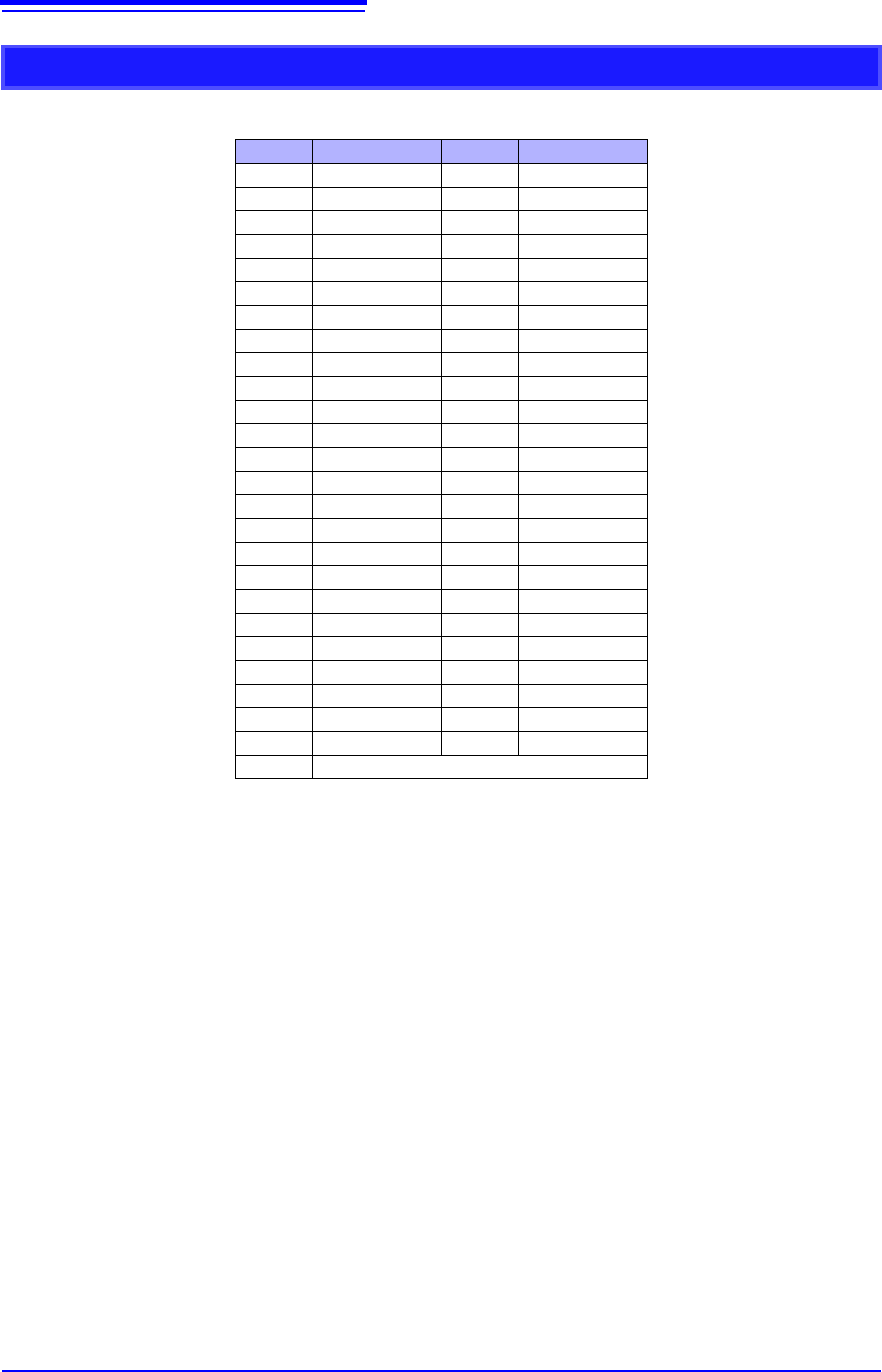
Output Connector Specifications
Pin Signal name Pin Signal name
1 I_GND 26 I_GND
2 CH1 7 I_GND
3 CH2 28 I_GND
4 CH3 29 I_GND
5 CH4 30 I_GND
6 I_GND 31 I_GND
7 CH5 32 I_GND
8 CH6 33 I_GND
9 CH7 34 I_GND
10 CH8 35 I_GND
11 I_GND 36 I_GND
12 NC 37 I_GND
13 NC 38 I_GND
14 NC 39 I_GND
15 NC 40 I_GND
16 I_GND 41 I_GND
17 NC 42 I_GND
18 NC 43 I_GND
19 NC 44 I_GND
20 NC 45 I_GND
21 I_GND 46 I_GND
22 TEST2 (DIN03)I 47 I_GND
23 TEST3 (DIN02) 48 I_GND
24 NC 49 I_GND
25 NC 50 I_GND
Frame F_GND
CH1 to CH8: Pulse output
I_GND: Isolation GND (insulated GND)
F_GND: Non-Isolation GND (main instrument GND)
NC: No Connect
TESTn: Test pin DO NOT CONNECT