MR8740、MR8741_user_manual_eng_20191016H.pdf - 第148页
6.8 Seeing Block Waveforms 136 This applies to the Memory function only. If recorded by memory division, the usage status of blocks can be checked. Furthermore, the desired block can be selected and the recorded waveform…

6.7 Switching the Waveform Screen Display (Display Menu)
135
5
Chapter 6 Waveform Screen Monitoring and Analysis
6
Select [Wave Width] to change the display width of the Waveform screen.
If a waveform is hard to see because of numeric value and settings information, this function can be
used to separate the waveform and other information.
The function is also active for the Channel settings window and Trigger settings window.
The screen changes each time you click [Format].
Click [Change Ch] to change the channels displayed at the bottom of the screen (CH1 to CH16 and
CH17 to CH32).
When level monitoring is ON: The channel displayed for analog monitoring changes.
When level monitoring is OFF: The channel displayed for the range setting changes.
Select [
]/[] to switch the displayed sheet.
The settings of each displayed sheet can be specified on the Unit List tab of the Channel settings
window.
See: Refer to "3.5.4 Display Sheet" (p.80)
6.7.3 Switching the Waveform Display Width
6.7.4 Switching the Format (MR8741 Only)
6.7.5 Changing the Monitor Values (MR8740 Only)
6.7.6 Switch the Displayed Sheet
6.8 Seeing Block Waveforms
136
This applies to the Memory function only.
If recorded by memory division, the usage status of blocks can be checked. Furthermore, the
desired block can be selected and the recorded waveform can be displayed.
When memory division is not used, depending on the record length, it is possible to display the last
16 measured waveforms.
See: "6.3 Moving the Waveform Display Position" (p.125)
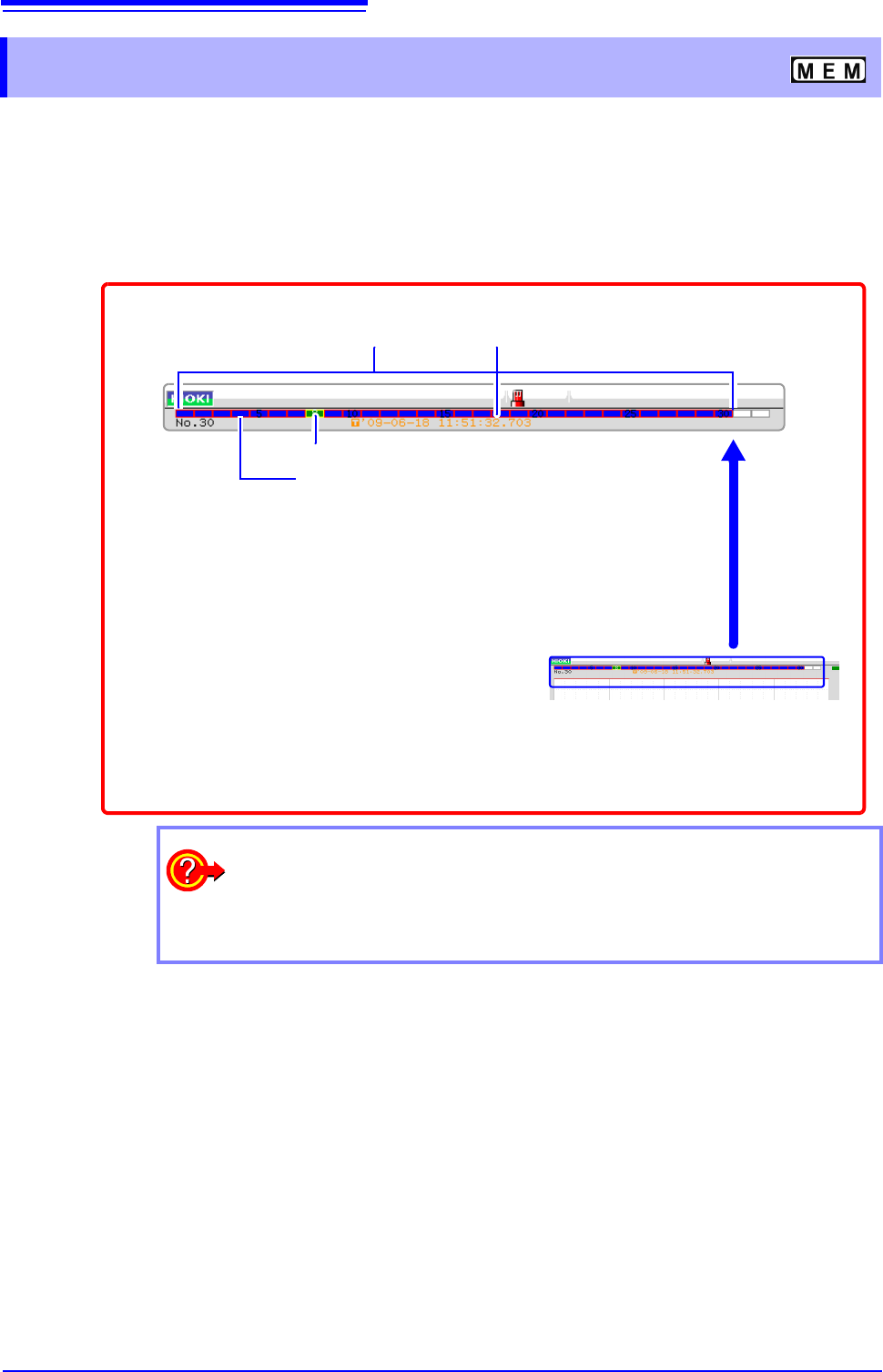
6.8 Seeing Block Waveforms
Data trigger time of the selected block
Blue blocks:
Saved blocks (blocks in use)
Green blocks: Currently selected displayed block
Blocks with light blue frame: Referenced blocks
1
Right-click and select [DISP] to display the
Waveform screen.
Left-click the rectangle of the block to display. When there are more than
32 blocks, click to the right side of the last block to display the next 32
blocks, and click to the left side of the first block to display the previous
32 blocks.
3
When the waveform display position is
displayed, left-click the WAVE button
on the top right of the screen to switch
to block display.
2
When you want to overlap with other blocks (reference blocks)
Open the Status screen to the [Memory Div] sheet and set
[Ref Block] to [On]
and select [All Blks On].
See: "11.2 Display Settings" (p.244)
137
6
Chapter 7 Utility Functions
7
Various utility functions are described in the section.
Utility Functions Chapter 7
Adding Comments (p.138)
Applicable measurements and settings
• Displaying Waveforms During Recording
(p.145)
• Overlaying with past recorded waveforms
(p.146)
Utility Functions
Converting input values (Scaling) (p.148)
Detailed module settings (p.161)
• Making anti-aliasing filter settings
• Selecting the thermocouple type
• Making reference point compensation settings
• Making wire break detection settings
• Making data updating settings
• Executing auto balance
• Making probe attenuation settings
• Making response settings
• Making measurement mode settings
Copying a setting to another channel(p.160)
Fine Adjustment of Input Values (p.158)
Inverting a waveform (p.159)
Setting the waveform display freely(p.155)