MR8740、MR8741_user_manual_eng_20191016H.pdf - 第203页
8.2 Setting the Trigger Mode 191 7 Chapter 8 T rigger Settings 8 Set whether to continue to accept triggers after mea suring. If all trigger sources are disabled (Off, with no trigger setting), measurement sta rts immedi…
8.1 Setting Workflow
190
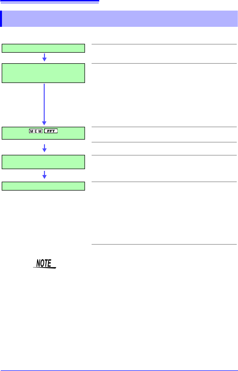
The procedure for making trigger settings is as follows.
8.1 Setting Workflow
Trigger Mode Settings
Set whether to continue to accept triggers after measuring. (p.191)
Trigger Type Settings
Make trigger source-related settings.
• Analog trigger
• Logic trigger
• Timer trigger
• External trigger
• Manual trigger
(p.192)
(p.197)
(p.199)
(p.203)
(p.203)
Pre-Trigger Settings
Set the amount to record before and after a trigger point.
(p.204)
Setting AND/OR Between Trigger
Sources
Select AND/OR logical combination of analog, logic, external
and timer triggers to be applied.
(p.208)
Start Measurement
Click [START] in the right-click menu to start measuring.
(However, operation differs according to the setting for Start Action
(p.311).)
Data acquisition starts when trigger criteria are met.
To stop measurement: Click [STOP] in the right-click menu.
Click once: recording stops at the end of the specified recording length.
Click twice: recording stops immediately.
Available settings for the respective items depend on the function.
• Except for manual trigger, triggering is based on the AND/OR combination of
trigger sources. (p.208)
• When triggering occurs, the TRIG OUT terminal for control of external devices
carries an output signal. (p.341) (MR8741 only)
• Settings for the analog trigger are restricted for the channel of the MR8990
Digital Voltmeter Unit.
• When MR8990 Digital Voltmeter Unit is installed, the trigger position may be
offset by 1 point.
8.2 Setting the Trigger Mode
191
7
Chapter 8 Trigger Settings
8
Set whether to continue to accept triggers after measuring.
If all trigger sources are disabled (Off, with no trigger setting), measurement starts immediately
(free-running).
Description Available selections depend on the function.
To Stop Measuring:
Click [STOP] in the right-click menu.
Click once: recording stops at the end of the specified recording length.
Click twice: recording stops immediately.
When the trigger mode is set to [Repeat]
During the processing interval from the end of recording until entering the next
trigger standby condition (Auto Save, waveform display processing, numerical
calculation), triggering will not be accepted.
8.2 Setting the Trigger Mode
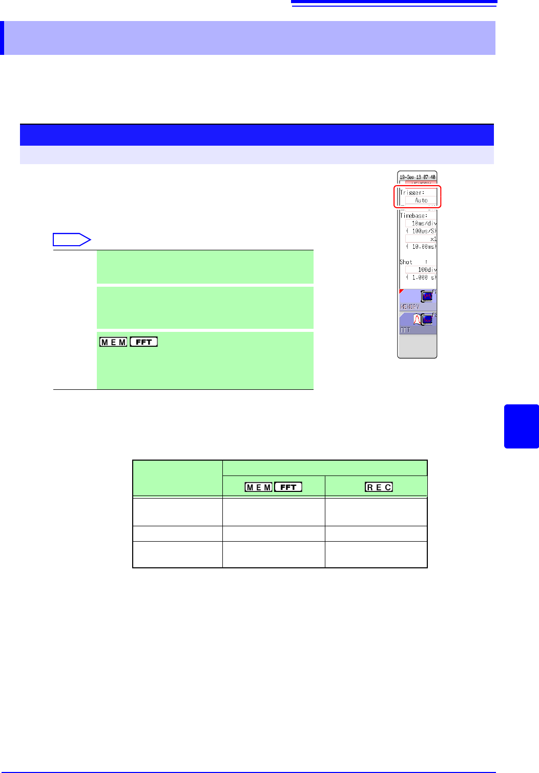
Procedure
To open the screen: Right-click and select [DISP] Waveform screen
1
Move the flashing cursor to the [Trigger] item.
2
Select the trigger mode.
Select
Single
Only one trigger is recognized. After measurement is start-
ed, once a trigger is applied, a waveform is recorded for the
specified recording length, and measurement then stops.
Repeat
Triggers are accepted continuously.
When no trigger is applied, the instrument enters the Trig-
ger Wait state. Click [STOP] to stop measuring. (See be-
low)
Auto
Triggers are accepted continuously.
If no trigger is applied within about one second, a waveform
of the specified recording length is automatically recorded.
Click [STOP] to stop measuring.
Trigger Mode
Function
Single
OO
(default setting)
Repeat OO
Auto
O
(default setting)
×
8.3 Triggering by Analog Signals
192
The steps for making settings and selecting the type of analog trigger are described below.
The Trigger settings window ([Analog Trg.] sheet) is used. An analog trigger cannot be set for the
channel of MR8990 Digital Voltmeter Unit.
8.3 Triggering by Analog Signals
8.3.1 Analog Trigger Settings and Types
Procedure
To open the screen: Right-click and select [DISP] Waveform screen Right-click and select [TRIG.SET]
Trigger settings window ([Analog Trg.] sheet)
1
Move the flashing cursor to the [Type] item of the channel for which to make
the setting.
2
Select the trigger type from the GUI displayed on the screen.
3
Use the mouse to move the flashing cursor to the parameter item.
4
Set the parameter value from the GUI displayed on the screen.
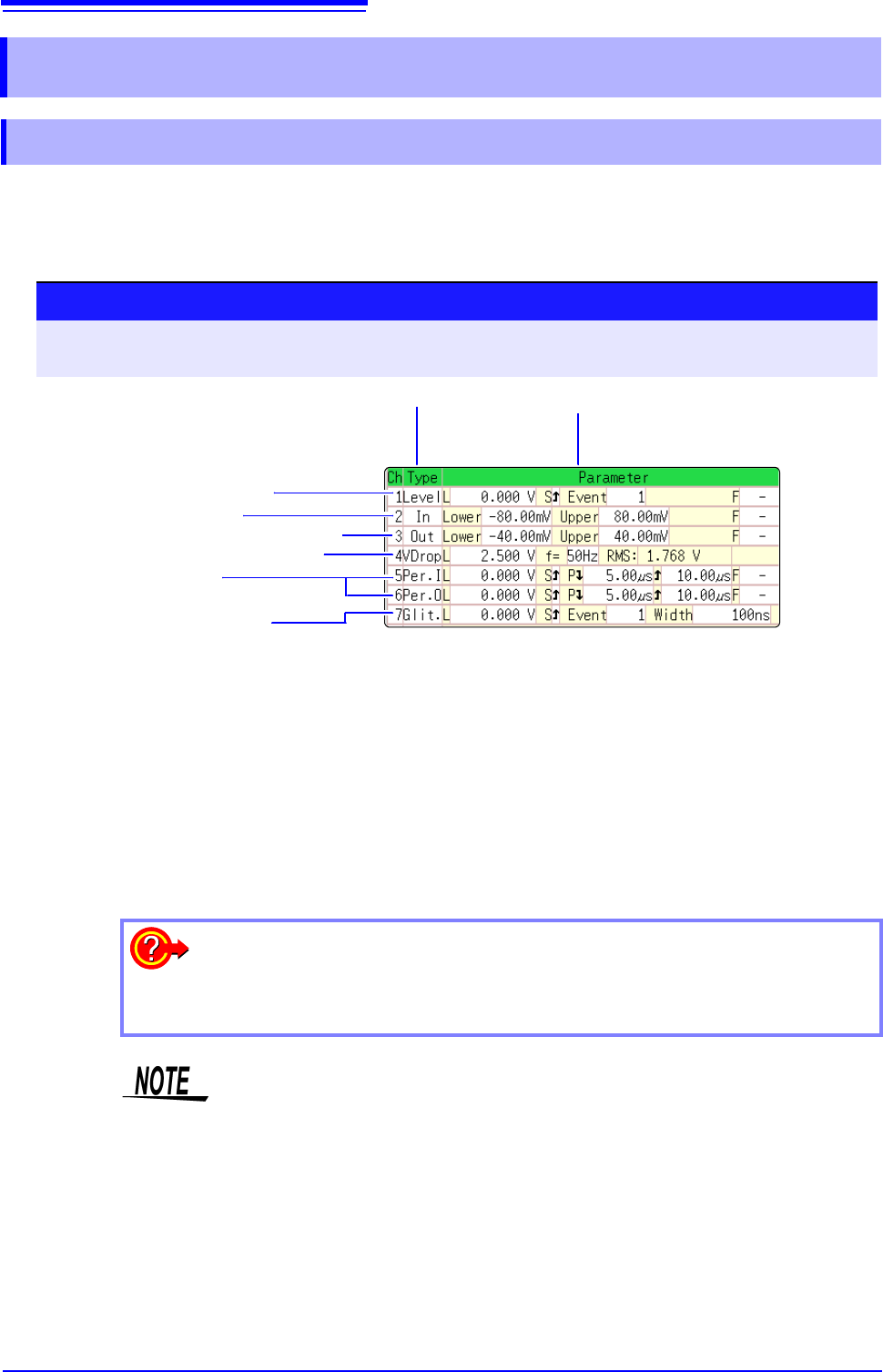
1 3
1. Level Trigger (p.193)
2. In-Window Trigger
Out-of-Window Trigger (p.193)
3. Voltage Sag Trigger (p.194)
4. In-Period Trigger
Out-of-Period Trigger (p.194)
5. Glitch Trigger (p.195)
To copy the setting to another channel
The Trigger settings window ([Analog Trig] sheet) can be used to copy a setting.
See:"7.8 Copying settings to other channels (calculation No.) (Copy function)" (p.160)
• When the FFT function is used and [Reference] item on the [Status] sheet is
set to [From Memory], an analog trigger cannot be set.
• Only the level trigger and window trigger can be set for the channel of the
MR8990 Digital Voltmeter Unit. The voltage drop trigger, periodic trigger and
glitch trigger cannot be set.