MR8740、MR8741_user_manual_eng_20191016H.pdf - 第69页
2.5 Setting the Clocks 57 2 Chapter 2 Measurement Prep arations Set date and time for the built-in clock as f ollows. The clock has an automatic cale ndar with leap year correction and 24-hour format. The functions liste…
2.4 Supplying Power
56
This section explains the correct procedure for powering the unit up or down.
2.4.2 Turning the Power On and Off
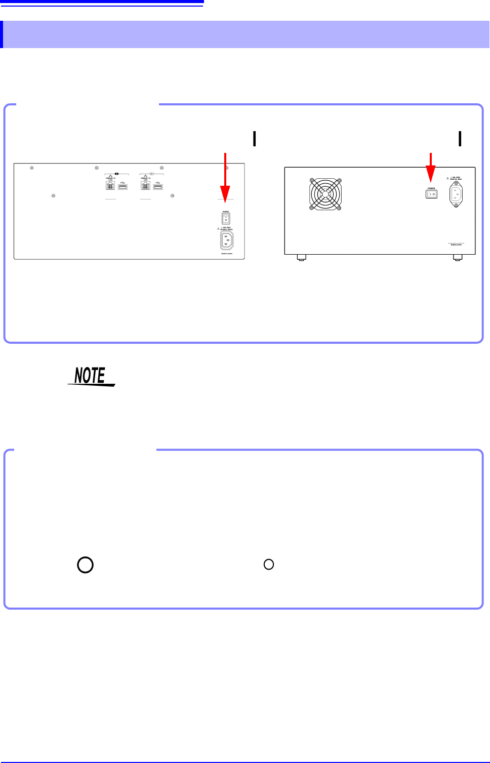
Turn the POWER switch on ( | ).
The startup screen appears first, and then the Waveform
screen is shown.
Power On
Turning Power On
Back Side
MR8740 MR8741
Power On
Before Starting Measurement
To obtain precise measurements, provide about 30 minutes warm-up after turn-
ing power on to allow the internal temperature of the modules to stabilize.
After that, perform zero adjustment before taking measurements.
Turn the POWER switch off ( ).
When power is turned on again, the display appears with the settings that
existed when power was last turned off.
Turning Power Off
Power Off
Recording Data
When the POWER switch is turned off, internal recorded data is erased. If
you don't want to lose recorded data, save it first to a USB memory stick.
See: "Chapter 4 Saving/Loading Data & Managing Files" (p.83)
Before Turning
Power Off
2.5 Setting the Clocks
57
2
Chapter 2 Measurement Preparations
Set date and time for the built-in clock as follows.
The clock has an automatic calendar with leap year correction and 24-hour format.
The functions listed below make use of the clock. Ensure that the clock is set correctly before using
these functions.
• Measurement with timer-based trigger
• Saving measurement data
2.5 Setting the Clocks
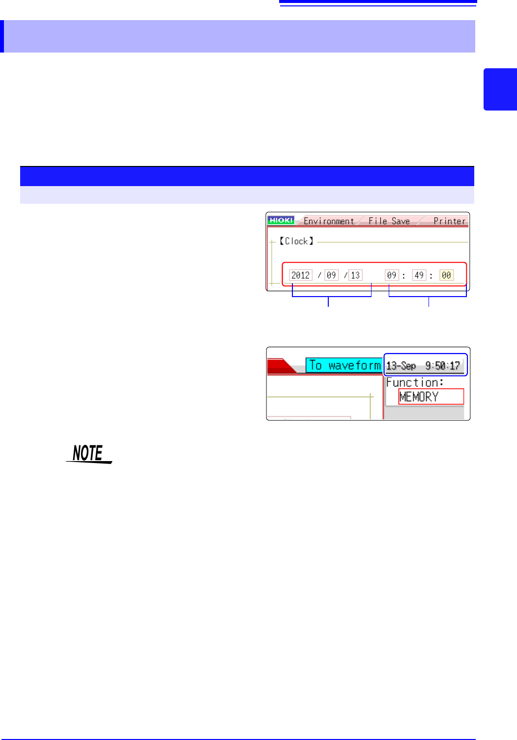
Date setting
(Year, Month, Day)
Time setting
(Hour, Minutes,
Seconds)
Procedure
To open the screen: Right-click and select [SYSTEM] [Init] sheet
1
Move the flashing cursor to the [Clock] item.
2
Select the digit to change and set the numeric
value.
3
When you select [Apply] while the flashing
cursor is on the [Clock] item, the clock is set
to the current date and time values.
The date and time indication is shown at the top right of the
screen.
The instrument contains a built-in backup lithium battery, which offers a service
life of about ten years. If the date and time deviate substantially when the instru-
ment is switched on, it is the time to replace that battery. Contact your dealer or
Hioki representative.
2.6 Adjusting the Zero Position (Zero-Adjust)
58
This procedure compensates for module differences and sets the reference potential of the instru-
ment to 0 V.
The compensation procedure is performed for all channels and ranges.
Perform zero-adjust in the following cases.
• When an module was changed.
• When power was turned off and on again.
• When settings were initialized (system reset).
• When DC/RMS is switched at the 8971Current Unit (model MR8740 only),
8972 DC/RMS Unit, or U8974 High Voltage Unit
• When measurement mode has been switched on Model U8979 Charge Unit.
• When the ambient temperature has changed significantly.
Zero-position drift
*
may occur.
* Drift: This refers to spurious output caused by a shift in the operating point of an opera-
tional amprifier. Drift can occur due to changes in temperature and due to compo-
nent aging over a period of use.
2.6 Adjusting the Zero Position (Zero-Adjust)
• To obtain precise measurements, provide about 30 minutes warm-up after turning power on to allow
the internal temperature of the modules to stabilize.
• Note that zero-adjust cannot be performed during a measurement.
• During zero-adjust, the mouse operation is disabled. (The procedure may take several seconds.)
Before starting zero-adjust
Procedure
To open the screen: Right-click and select [CHAN] [Unit List] sheet
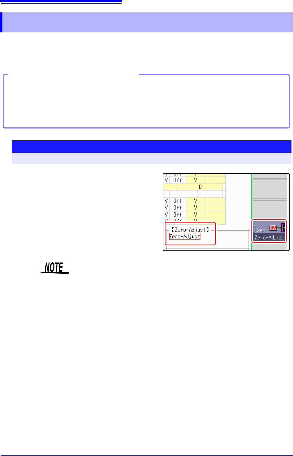
1
Move the flashing cursor to the [Zero-Adjust]
item.
2
Select [Exec Zero-Adjust].
The zero-adjust procedure is carried out.
• Zero-adjust has no effect on the 8969 and U8969 Strain Unit.
(Perform zero-adjust using Auto Balance.)
See:"7.9.4 Setting Model 8969 and U8969 Strain Unit" (p.165)
• MR8990 Digital Voltmeter Unit performs calibration when zero adjustment is
performed.
See:"2.7 Performing Calibration (When Mounting MR8990)" (p.59)